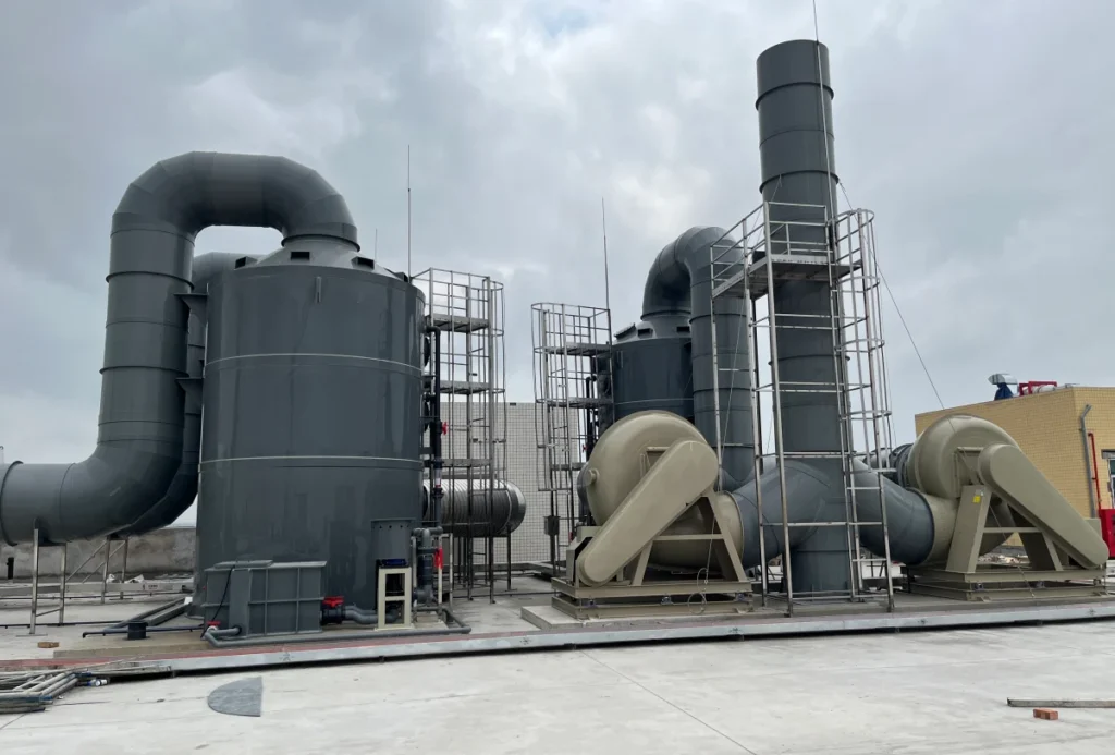
A PP pump for wet scrubber duty has one job: it takes liquid out of the sump and puts it back into the tower at the flow and pressure the nozzles need. It never leaves the circuit. That single fact changes every number in the selection, because a closed loop carries almost no static head and a great deal of friction, and its flow is set by a ratio rather than by a production rate.
This guide works through the four decisions that fix the pump: the L/G ratio that sets the flow, the three terms that add up to the head, the turndown the plant will actually run at, and the solids the loop concentrates. It closes with the arrangement question, including the duty for which polypropylene is the wrong answer.
Key takeaways
- A scrubber recirculation pump runs in a closed loop, so friction and nozzle pressure set the head, not lift.
- Liquid flow is the gas flow multiplied by the L/G ratio; the EPA manual puts the venturi optimum at 7–10 gal per 1,000 ft³, about 0.9–1.3 litres per cubic metre.
- Raising L/G above that band costs pumping power without a significant gain in collection.
- The head has three terms — static, friction and nozzle — and the nozzle term is usually the largest, and the one a pump supplier cannot give you.
- A friction-dominated loop suits a variable-frequency drive, but every centrifugal pump has a minimum flow below which the impeller recirculates and damages itself.
- A recycle loop concentrates the solids it captures; blowdown and strainers are part of the pump’s operating conditions, not an afterthought.
- Polypropylene is the right wet-end material for aggressive chemistry and the wrong one for an abrasive duty; those are two different problems.
What a PP Pump Does in a Wet Scrubber
In a wet scrubber the pump is part of a liquid circuit, not a transfer line. The EPA Cost Manual describes the liquid storage and delivery system as “a recirculation tank, pump, filters, valves, piping, pressure gauges, and flow meters”, and notes that most systems are designed as recycle systems. A PP pump for wet scrubber service sits inside that circuit with its wetted end — casing, impeller and cover — in contact with the scrubbing liquor, while its shaft, bearings and motor stay outside it.
Which of those parts the liquor actually reaches, and which of them fail before the casing does, is covered in centrifugal pump parts.
The loop is closed, and that changes the whole calculation
The DOE sourcebook draws the distinction that matters here. In a closed-loop system “the frictional losses of system piping and equipment are the predominant pump load”, while static head enters mainly in open-loop systems where liquid is moved from one place to another. A scrubber loop is closed. The pump is not lifting liquid to a destination; it is pushing it around a circuit, up to the header, out of the nozzles, and back down the tower wall into the same sump.
That is why a scrubber pump’s head is often much smaller than the tower height suggests, and why the nozzle, not the tower, is the part of the circuit that sets it. The general method for turning flow and head into a pump selection is set out in our polypropylene pump selection guide; what follows is the part that is specific to scrubbing.
What the liquid delivery system contains
The EPA manual places filters between the sump and the pump, and pressure gauges and flow meters downstream of it. Both matter to the pump. A strainer on the suction side adds resistance that belongs in the NPSH calculation, and a flow meter downstream is how you discover that the nozzles have partly blocked and the duty point has moved left along the curve. For the tower side of the system, the wet scrubber design guide covers the vessel and packing; this page stays with the liquid loop.
Liquid Flow Comes From the L/G Ratio
The number that sizes the pump is not the tower diameter, and it is not the gas flow on its own. It is the liquid-to-gas ratio. The EPA manual defines L/G as “the volume of liquid injected per volume of waste gas treated”.
The ratio and its published range
For a venturi scrubber the manual gives a working band: “Liquid flow rates between 7 and 10 gal/1000 ft³ give optimum performance”, and ratios above 10 gal/1000 ft³ “do not improve the scrubber performance significantly”. It also gives the reason not to go higher anyway — operating costs rise “due to greater scrubbing liquid and pump usage”.
Those figures are in US units. Converted, 7 to 10 gal per 1,000 ft³ is about 0.94 to 1.34 litres per cubic metre of gas. For a spray tower collecting fine particulate the manual quotes a much higher figure, over 20 gal/1000 ft³, which is about 2.7 L/m³.
For an absorption tower rather than a particulate scrubber, the second EPA chapter constructs the ratio differently: the minimum L/G read from the equilibrium line is multiplied by “an adjustment factor, commonly between 1.2 and 1.5”. Either way, the pump sees a liquid rate derived from a ratio, not from a tank level.
A worked example at 40,000 m³/h
Take a scrubber handling 40,000 m³/h of gas at an L/G of 1.3 L/m³. The circulating liquid rate is 40,000 × 1.3 ÷ 1,000 = 52 m³/h. That is the flow the pump is bought for.
| Waste gas flow (m³/h) | L/G 0.9 L/m³ | L/G 1.3 L/m³ | L/G 2.7 L/m³ |
|---|---|---|---|
| 10,000 | 9.0 m³/h | 13.0 m³/h | 27.0 m³/h |
| 20,000 | 18.0 m³/h | 26.0 m³/h | 54.0 m³/h |
| 40,000 | 36.0 m³/h | 52.0 m³/h | 108.0 m³/h |
| 60,000 | 54.0 m³/h | 78.0 m³/h | 162.0 m³/h |
Note on the figures — circulating liquid rate = gas flow × L/G ÷ 1,000. The three ratios are the EPA venturi band (7–10 gal/1000 ft³) and the spray-tower figure (over 20 gal/1000 ft³) converted to litres per cubic metre.
The table shows why the L/G choice matters more than the gas flow. Doubling the gas flow doubles the liquid rate, but moving from 0.9 to 2.7 L/m³ triples it at any gas flow. A pump specified on airflow alone can be out by a factor of three.
Head Is Three Terms, and Only One Is a Lift
Static, friction and nozzle
The pump’s total head is the sum of three terms, and they are calculated separately.
The static term is the vertical distance from the sump liquid level to the nozzle header. It is a tape measure, not a calculation, and in a scrubber it is usually the smallest of the three.
The friction term is the loss in the recirculation piping, fittings and valves at the design flow. It rises roughly with the square of flow, so it is the term that moves when the pump is turned down.
The nozzle term is the pressure the nozzle manufacturer requires at the inlet, converted to metres of the pumped liquid. It is usually the largest of the three, and it is the one number in the sum that the pump supplier cannot know.
Why a “25 m pump” is not a 25 m lift
A pump quoted at 25 m of head on a scrubber is not lifting liquid 25 m. In the example below the lift is 6 m, and the nozzle accounts for 14.6 m of the 24.6 m total.
| Term | Value | Head equivalent |
|---|---|---|
| Static lift, sump level to nozzle header | 6.0 m | 6.0 m |
| Piping and fitting loss at design flow | 4.0 m | 4.0 m |
| Nozzle pressure, 1.5 bar at SG 1.05 | 150.0 kPa | 14.6 m |
| Total head | 24.6 m |
Note on the figures — the six metre lift, four metre pipe loss and 1.5 bar nozzle pressure are inputs chosen for this example, not standard values. Head equivalent = pressure ÷ (ρ × g), with ρ = 1,050 kg/m³.
Two consequences follow. The nozzle pressure is the term to confirm in writing before the pump is ordered, because it is the one number the pump supplier cannot supply. And because pressure converts to a different height for a different fluid, the same 1.5 bar is 15.3 m in water and 12.7 m at a specific gravity of 1.2.
Turndown: The Pump Lives Away From Its Duty Point
What slows down when the plant slows down
A scrubber on a process running at 60 percent of design gas flow still has to hold its L/G ratio, so the liquid rate falls with the gas rate. The pump then operates far from the point it was selected at, and the question becomes what the circuit does when it gets there.
The affinity laws and the minimum flow rating
In a friction-dominated loop the system curve and the affinity laws agree. Reduce speed to 80 percent and flow falls to 80 percent, head to 64 percent, and shaft power to about 51 percent. The DOE sourcebook notes that adjustable speed drives are “especially practical for systems that are dominated by frictional resistance”, which describes a scrubber recirculation loop closely.
| Speed | Flow (m³/h) | Head (m) | Shaft power (kW) |
|---|---|---|---|
| 100% | 52.0 | 24.6 | 6.64 |
| 90% | 46.8 | 19.9 | 4.84 |
| 80% | 41.6 | 15.7 | 3.40 |
| 70% | 36.4 | 12.0 | 2.28 |
| 60% | 31.2 | 8.8 | 1.44 |
Note on the figures — computed from the worked example by the affinity laws: flow ∝ speed, head ∝ speed², power ∝ speed³.
The same sourcebook supplies the warning that applies at the bottom of that table: discharge recirculation effects “usually result from operating a pump at a flow rate that is too low”, and “many pumps are listed with a minimum flow rating”. A turndown that takes the pump below its minimum continuous flow damages the impeller from the inside, and the energy saving does not pay for it.
The practical answer is a minimum-flow bypass, or a speed floor set from the pump’s own rating rather than from the process turndown.
Solids and Salts: Where the Loop Actually Fails
A recycle loop concentrates what it captures
A scrubber captures solids and keeps the liquid. The EPA manual is direct about the consequence: “the solids content of the liquid increases as PM is collected”, and the concentration “must be maintained below a design limit or the spray characteristics of the system cannot be maintained”.
The arithmetic is worth doing before the pump is chosen. At an inlet loading of 1.0 g/m³ and 40,000 m³/h of gas, the tower captures 40 kg/h. Spread through 52 m³/h of circulating liquid, that is about 0.8 g/L — a slurry rather than water, unless blowdown removes it.
Strainers, sump volume and blowdown
Three things keep the pump out of trouble: a strainer upstream of it, a sump large enough that solids can settle somewhere other than the impeller, and a blowdown rate set from the capture rate rather than from the make-up water budget. The EPA manual lists filters as part of the delivery system for exactly this reason, and places them before the pump.
Why PP is the wrong material for an abrasive duty
Polypropylene resists chemistry well and abrasion badly. A slurry at 0.8 g/L is routine for a pump with a wear-resistant wet end, and it is a wear problem for a polymer that is soft by comparison with metal. Where the solids are abrasive — sand, grit, oxide scale — the wet end belongs in a rubber-lined or metal pump. A PP pump bought for that duty loses its clearances first and its performance second.
Suction From a Sump, at Scrubber Temperature
Submergence and vortexing
A wet scrubber pump beside a sump draws through a suction line, so the sump geometry is part of the pump’s suction condition. Too little submergence above the suction inlet lets a vortex form and the pump take air. A suction line that is too long or too narrow spends NPSH available before the liquid reaches the impeller, and a strainer in that line spends more of it.
Warm liquor cuts NPSH available
Scrubber liquor is often the warmest liquid in the plant, because it has just taken heat out of the gas. Water’s vapour pressure rises steeply with temperature, and every unit of it comes straight off NPSH available. The DOE sourcebook’s design convention — NPSH available at least 25 percent above NPSH required at all expected flow rates — is easiest to break on a hot loop.
The mechanisms that produce it, and the three measurements that separate them, are covered in pump cavitation.
Two habits follow for the scrubber specifically. Confirm the liquor temperature at the pump, not at the tower inlet, because a quench section upstream can leave the sump much hotter than the number on the process sheet. And check the margin at the lowest liquid level the sump will ever reach, not at normal level.
Which Arrangement Fits, and What We Build
Horizontal PP, vertical immersed, magnetic drive
Three arrangements are common in scrubber service, and they are not interchangeable.
| Arrangement | What it buys | What it costs | Where it fits |
|---|---|---|---|
| Horizontal PP centrifugal | Maintenance at floor level, replaceable seal, lower cost | Needs a suction line; the seal is a failure point | Sump at grade, normal access |
| Vertical immersed | No suction line, no external leakage path | Bearings above the liquid, lower efficiency, lifting gear for maintenance | Pits and confined spaces |
| Magnetic drive | Sealless, zero leakage | Cannot run dry, decoupling and overheating risk, lower efficiency | Strong chemistry with a zero-leak requirement |
The honest limits of a horizontal PP pump here
We build the horizontal polypropylene centrifugal pump. We do not build vertical immersed pumps or magnetic-drive pumps, and a scrubber that needs either of those is not a scrubber we should be quoting a horizontal pump for. The PP centrifugal pump range covers 0.75 to 7.5 kW, which is the size band the worked example above lands in.
Which pump types can be built in solid polypropylene at all, and which are simply outside our range, are two different statements. Both are set out in types of centrifugal pump.
What a PP pump for wet scrubber duty does well: aggressive liquor at moderate temperature and moderate head, with the pump at grade and room to change a seal. What it does not do: deep sumps, zero-leakage requirements, abrasive slurries, and duties above the band in which polypropylene’s strength is documented. ISO 3213:1996 gives reference lines for expected PP strength between 20 °C and 95 °C, and above that band the thermoplastic counterpart named in ISO 15494 is PVDF, specified under ISO 10931.
Where the material being weighed against polypropylene is stainless rather than PVDF, the decision turns on chloride stress corrosion cracking against the PP temperature ceiling; that comparison is set out in the polypropylene pump vs stainless steel article.
For the wider hardware set around the loop, the wet scrubber systems range and the industrial water pump range show where a PP centrifugal pump sits in the package.
Frequently Asked Questions
Can a PP pump handle scrubber liquor?
For the chemistry, usually yes: PP handles dilute mineral acids, alkalis, hypochlorite at ambient temperature and many salt solutions. For the duty, it depends on two things the chemistry does not describe — temperature and solids. Confirm the liquor temperature at the pump against the ISO 3213 range, and the solids loading against the fact that PP is a soft polymer. Aggressive but clean liquor is PP’s job; abrasive liquor is not.
What L/G ratio should I design for?
There is no single answer, because the ratio follows the scrubber type and the pollutant. The EPA manual gives 7–10 gal per 1,000 ft³ (about 0.9–1.3 L/m³) as the venturi optimum and notes that higher ratios cost pumping power without a significant gain. For a spray tower on fine particulate it quotes over 20 gal/1,000 ft³ (about 2.7 L/m³). For an absorption tower the ratio comes from the equilibrium line multiplied by 1.2–1.5. Start from the scrubber design, then size the pump from the resulting liquid rate.
Why does my scrubber pump keep failing?
Three causes account for most of it. Solids: a recycle loop concentrates what it captures, and a strainer cleaned weekly on a loop capturing 40 kg/h is not a solids control strategy. Suction: a warm sump and a long suction line spend NPSH available until the impeller cavitates. Minimum flow: a pump turned down for a low-load shift runs below its minimum continuous flow and recirculates inside its own casing. All three are visible in the pump’s operating data before the failure.
Do I need a VFD on a scrubber recirculation pump?
Often yes, because a scrubber is a friction-dominated loop and that is the case the DOE sourcebook identifies as suited to adjustable speed. Two conditions apply: the speed range must keep the pump above its minimum flow rating, and the L/G ratio must still be met at the reduced gas flow. If the plant turndown is small, a fixed-speed pump with a throttling valve may be simpler; if it is large, the drive usually pays.
Can I use a stainless steel pump instead?
Sometimes. 316 stainless is efficient and mechanically stronger than PP, and it handles many neutral and mildly corrosive liquors. It is the wrong choice for chlorides at temperature, for hypochlorite, and for dilute acids where the corrosion rate is high enough to matter. The decision is the liquor’s chemistry and temperature together, not the metal’s reputation.
What size pump does a 20,000 m³/h scrubber need?
At an L/G of 1.3 L/m³ the circulating rate is 26 m³/h. The head then comes from the sump-to-header height, the piping loss and the nozzle pressure; with 6 m, 4 m and 1.5 bar at a specific gravity of 1.05 the total is about 24.6 m. At an efficiency of 0.55 that is roughly 3.3 kW of shaft power, so a 4 kW motor. Raise the L/G to 2.7 and the flow doubles to 54 m³/h, and the motor roughly doubles with it.
Sources
- U.S. Environmental Protection Agency, Office of Air Quality Planning and Standards. Air Pollution Control Cost Manual, Section 6, Chapter 2: Wet Scrubbers for Particulate Matter. Sections 2.2.2.1 (spray tower L/G), 2.2.2.6 (orifice scrubber), 2.3.1 (liquid storage and delivery system), 2.4.1.1 (liquid-to-gas ratio). epa.gov
- U.S. Environmental Protection Agency, Office of Air Quality Planning and Standards. Air Pollution Control Cost Manual, Section 5.2, Chapter 1: Wet Scrubbers for Acid Gas. Sections 1.2.4 (recirculation of the solvent), 1.3.1 (L/G adjustment factor), 1.5.1 (direct annual costs). epa.gov
- U.S. Department of Energy, Industrial Technologies Program. Improving Pumping System Performance: A Sourcebook for Industry, 2nd edition, 2006. Pages 8 (closed-loop systems, discharge recirculation, minimum flow rating), 17 (adjustable speed drives), 38 (NPSH margin). energy.gov
- International Organization for Standardization. ISO 3213:1996, Polypropylene (PP) pipes — Effect of time and temperature on the expected strength. Scope and clause 4. iso.org/standard/22752.html
- International Organization for Standardization. ISO 15494:2015, Plastics piping systems for industrial applications — PB, PE, PE-RT, PE-X, PP. Introduction, naming ISO 10931 as the PVDF counterpart. iso.org/standard/55627.html