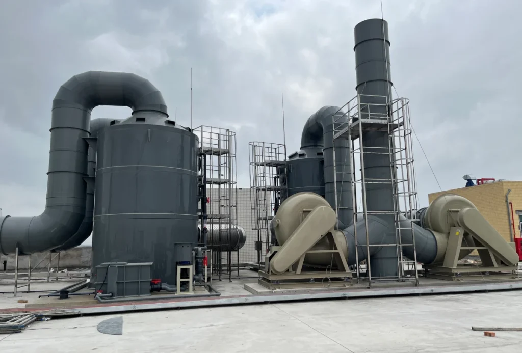
A polypropylene pump is chosen by four numbers: flow, head, specific gravity and temperature. Every other line on the data sheet — impeller diameter, motor frame, seal faces, flange size — follows from those four. When a quotation arrives without them, the supplier is guessing, and so is the buyer.
This guide takes each of the four in turn, with a worked example that stays fixed from the first table to the last. It also covers the two failures a polypropylene wet end cannot survive: cavitation, and running above the range the polymer was rated for. Both are installation problems rather than material problems, and both are visible before the pump is ordered.
Key takeaways
- Four inputs — flow, head, specific gravity and temperature — decide every other line on a polypropylene pump data sheet.
- Head is not pressure. The same 25 m of head is 2.45 bar in water and 3.68 bar at a specific gravity of 1.5.
- Shaft power rises in direct proportion to specific gravity, so a motor sized on water can be overloaded by the fluid alone.
- NPSH available falls steeply as temperature rises, because water’s vapour pressure rises steeply; a system that works at 20 °C can cavitate at 80 °C.
- A cavitated polypropylene impeller is replaced, not repaired — there is no weld repair on a honeycombed PP surface.
- Polypropylene’s documented strength range runs from 20 °C to 95 °C; above that the honest answer is PVDF, not a thicker wall.
- Compatibility is a function of chemical, concentration and temperature together, and the only answer that binds is the supplier’s written confirmation for the specific duty.
What a Polypropylene Pump Is in Chemical Service
In a polypropylene pump, polypropylene is the wetted end. That means the casing, the impeller and, in most designs, the casing cover and the seal housing. The shaft is metal, the bearing frame is metal and the motor is a standard motor. The material decision is therefore about what the fluid touches, not about what the machine is.
The full list of what stays polymer and what stays metal in a PP pump is set out in centrifugal pump parts, together with which of those parts is designed to wear out first.
The wetted end is the material decision, not the motor
A solid polypropylene pump has a moulded or machined PP casing and a PP impeller. A lined pump has a metal casing with a PP liner inside it. The solid version is lighter and has no liner-to-metal bond line to open on a thermal cycle, but the polymer carries the full pressure load and therefore sets both the pressure and the temperature ceiling. The lined version puts the pressure load on metal and the corrosion duty on the liner, which reaches higher pressures at the cost of an interface that has to survive the same thermal cycles.
For scrubber recirculation, chemical transfer and plating-line duty at moderate pressure, the solid PP pump is the usual starting point. The industrial water pump range is arranged by that distinction.
Four families are sold in PP, and only one is sized in this guide
Polypropylene pumps are sold in four families: centrifugal, magnetic-drive centrifugal, diaphragm and drum. The first two share the same hydraulics and differ in how the shaft is sealed, so the arithmetic below applies to both. Diaphragm pumps are sized on displacement and air pressure; drum pumps on drum depth and viscosity. Those are different calculations.
This guide sizes the centrifugal family only, because that is where flow, head, specific gravity and temperature interact in a way that can be read off a curve. The polypropylene centrifugal pump line is the hardware the rest of this article describes.
Inside that family the pump can still be single stage or multistage, end suction or inline, horizontal or vertical, and the arrangement decides how much of it a polymer casing can carry. Those three classifications are set out in types of centrifugal pump.
The Four Numbers That Decide the Pump
A pump quotation that does not ask for all four of these is a quotation for a shape. Here is what each one moves.
| Input | Unit | What it changes | What happens if it is missing |
|---|---|---|---|
| Flow, Q | m³/h | Pump size and impeller diameter | The pump is selected too large or too small |
| Head, H | m | Number of stages, speed, motor power | The duty point is never reached |
| Specific gravity, SG | — | Discharge pressure and shaft power | The motor is overloaded by the fluid alone |
| Temperature, T | °C | PP pressure rating and NPSH available | The casing deforms, or the impeller cavitates |
Flow, head, specific gravity and temperature
Flow and head place the duty point on the curve. Specific gravity converts that head into a pressure and a shaft power. Temperature does two things at once: it lowers the strength of the polymer and it raises the vapour pressure of the liquid, so it sets both the pressure ceiling and the suction margin. A specification that carries flow, head and temperature but not specific gravity is still incomplete, because a pump that is right for water is wrong for a 1.5 specific gravity liquor at the same duty point.
The worked example used through the rest of the guide
From here on the duty is fixed at 20 m³/h at 25 m of head, with a pump efficiency of 0.55. The fluid is left unspecified on purpose. The next sections show what happens to the same pump as the fluid changes, which is the whole point of naming specific gravity separately from flow and head.
Flow and Head: Reading Two Curves Together
The pump curve is what the supplier promises
A centrifugal pump curve plots head against flow at one speed and one impeller diameter. It falls from left to right: shut-off head at zero flow, and a maximum flow at zero head. A polypropylene pump’s curve has the same shape as a metal pump’s. The material changes efficiency and the pressure rating, not the geometry of the curve.
The system curve is what your installation demands
The system curve is the head the installation consumes at each flow: the static lift, which does not change with flow, plus friction, which rises roughly with the square of flow. It starts at the static lift at zero flow and bends upward. Suction lift, pipe length, valve position and the elevation of the discharge point all enter here, and none of them are on the pump data sheet.
The duty point, and why the affinity laws matter
The duty point is where the two curves cross, and it is the only flow and head the pump will actually deliver. Move the impeller diameter and the pump curve moves with it. The relations are the affinity laws: flow varies with impeller diameter, head with diameter squared, and brake horsepower with diameter cubed (DOE, p. 49). The same form holds for speed — flow with speed, head with speed squared, power with speed cubed — which is why a variable-frequency drive is a flow-control device as well as an energy device.
The cubed term is the one that surprises people. Trim 10 percent off the impeller diameter and you lose about 10 percent of flow, about 19 percent of head, and about 27 percent of power. Go the other way and the motor has to grow at the same cubic rate, which is why oversizing an impeller to “have some in reserve” is not a small decision.
Specific Gravity Turns Head Into Pressure
Pressure from head
Head is a length; pressure is what that length of fluid weighs. The relation is the product of density, gravity and head. For water at a specific gravity of 1.0, 25 m of head is 245 kPa, or 2.45 bar. The same 25 m at a specific gravity of 1.5 is 368 kPa, or 3.68 bar. Nothing on the pump changed.
The DOE sourcebook defines specific gravity as the ratio of the fluid density to the density of water under standard conditions (p. 94). That definition is why specific gravity enters every pressure and power calculation as a plain multiplier, with no correction factor attached.
Shaft power from flow, head and efficiency
Fluid power is the product of density, gravity, flow and head. Shaft power is fluid power divided by pump efficiency. The DOE sourcebook states the same thing from the other end: it calculates fluid power from the specified flow rate, head and specific gravity (p. 57). The efficiency figure is the supplier’s, and it belongs to the duty point, not to the pump in general.
The 1.0 SG assumption is where oversizing starts
A motor selected on water is selected at a specific gravity of 1.0. The table below holds flow, head and efficiency fixed and changes only the fluid.
| Specific gravity | Discharge pressure (kPa) | Discharge pressure (bar) | Fluid power (kW) | Shaft power (kW) | Next motor size |
|---|---|---|---|---|---|
| 1.00 | 245.2 | 2.45 | 1.36 | 2.48 | 3.0 kW |
| 1.10 | 269.8 | 2.70 | 1.50 | 2.73 | 3.0 kW |
| 1.20 | 294.3 | 2.94 | 1.64 | 2.97 | 3.0 kW |
| 1.35 | 331.1 | 3.31 | 1.84 | 3.34 | 4.0 kW |
| 1.50 | 367.9 | 3.68 | 2.04 | 3.72 | 4.0 kW |
Note on the figures — computed for Q = 20 m³/h, H = 25 m and η = 0.55, with density equal to 1,000 kg/m³ times the specific gravity and g = 9.81 m/s². Motor sizes are the next standard size above the shaft power.
The step from 1.0 to 1.5 raises shaft power from 2.48 kW to 3.72 kW — 50 percent, exactly in proportion — and moves the next standard motor size from 3.0 kW to 4.0 kW. A quotation that does not name the specific gravity has, in effect, quoted a water pump. The centrifugal water pump specification is the right reference only when the fluid really is water.
NPSH and Cavitation: The Failure PP Cannot Repair
NPSH available versus NPSH required
NPSH available is set by the system; NPSH required is set by the pump. The DOE sourcebook states the split plainly: NPSHA “is a function of the system and the flow rate”, while NPSHR “is a function of the pump and the flow rate” (p. 38). NPSHR is normally quoted as NPSH3, the value at which total head falls by 3 percent as the impeller begins to cavitate, a definition the sourcebook attributes to the Hydraulic Institute.
The same sourcebook gives the design convention that matters here: “A common rule in system design is to ensure that NPSHA is 25% higher than NPSHR for all expected flow rates” (p. 38). That is a margin on the worst flow in the range, not on the design point alone.
Why a cavitated PP impeller is a replacement, not a repair
Cavitation collapses vapour bubbles against the impeller surface. In metal the damage is a pitted or spongy area that a weld shop can sometimes dress back. In polypropylene the same collapse erodes the polymer into a honeycombed surface with no structural value left. There is no weld repair that restores a moulded impeller, and a patch would change the balance of the rotor. The part is replaced, and the cost of the replacement sits on top of the cost of the cause.
Three installation fixes that cost nothing
Because NPSHA belongs to the system, the cheapest fixes are plumbing rather than hardware. Raise the suction level, or feed the suction from a head tank, to reduce the lift. Shorten and enlarge the suction line, and remove the elbow directly at the inlet. Reduce the temperature, or move the pump so that the suction source is cooler. None of the three changes the pump.
Why that plumbing works, how to tell vapour cavitation from gas entrainment and internal recirculation, and what to do when the arithmetic cannot be closed, are set out in cavitation in centrifugal pump service.
The table below uses the worked example with an atmospheric pressure of 101.325 kPa (10.33 m of water), a suction liquid level 2.0 m below the pump, and 0.8 m of suction-line friction loss.
| Liquid temperature | Vapour pressure (kPa) | Vapour head (m) | NPSH available (m) | Margin over 4.0 m NPSHR |
|---|---|---|---|---|
| 20 °C | 2.33 | 0.24 | 7.29 | +82.3% |
| 40 °C | 7.48 | 0.76 | 6.77 | +69.2% |
| 60 °C | 20.18 | 2.06 | 5.47 | +36.8% |
| 80 °C | 47.42 | 4.83 | 2.69 | −32.6% |
Note on the figures — vapour pressure computed from the NIST Chemistry WebBook Antoine parameters for water (Stull, 1947), converted to metres of water at ρ = 1,000 kg/m³ and g = 9.81 m/s². NPSH available = 10.33 − vapour head − 2.0 − 0.8.
At 20 °C the system carries a large margin over a pump requiring 4.0 m. At 80 °C the same pipes, the same pump and the same flow produce a negative margin. The only thing that changed was the vapour pressure of the liquid, and it changed by a factor of twenty between the first row and the last.
Temperature Sets the Real Pressure Ceiling
What heat does to polypropylene
Polypropylene does not have a single pressure rating. It has a strength that falls as temperature rises and continues to fall as the load is held. ISO 3213:1996 expresses this as reference lines — “the minimum values for expected strength as a function of time and temperature” — for PP-H, PP-B and PP-R, and its fourth clause states that “the reference lines for temperatures between 20 °C and 95 °C are described by the following equations”.
Two things follow. Any PP pressure figure quoted without a temperature and a design life is incomplete, because it is one point on a family of lines. And the standard’s documented range runs from 20 °C to 95 °C, so a duty above that range falls outside what the reference lines describe.
When PVDF is the honest answer
Above the PP range the answer is not a thicker wall. Wall thickness buys back stress at a fixed temperature; it does not move the temperature at which the polymer softens. PVDF is the thermoplastic that the industrial piping standards treat as PP’s higher-temperature counterpart: ISO 15494:2015, which covers PB, PE, PE-RT, PE-X and PP for industrial applications, names ISO 10931 as the corresponding standard for PVDF. Where the duty needs it, the wet end moves to PVDF or to a lined metal pump.
| Condition | What the standard covers | What to do |
|---|---|---|
| Continuous duty inside 20–95 °C | ISO 3213 reference lines describe expected PP strength across this band | Evaluate the duty against the supplier’s rating at that temperature |
| Continuous duty above 95 °C | Outside the band the reference lines describe | Move the wet end to PVDF (ISO 10931) or a lined metal pump |
| Aggressive chemical at temperature | ISO 175 immersion testing is the method behind a compatibility chart | Obtain written confirmation for the concentration and temperature |
| Abrasive slurry | PP is a soft polymer with no wear surface | Use a rubber-lined or metal wet end |
| Cavitating duty | PP has no weld repair for an eroded impeller | Fix NPSH available before changing the pump |
What PP Handles and What It Does Not
The families PP handles well
Polypropylene is a sound wet-end material for dilute and moderate mineral acids, for alkalis, for salt solutions, for sodium hypochlorite at ambient temperature, and for a wide range of solvents. It is also the practical choice where the casing has to be moulded to a shape or fitted with a non-standard connection, which is why it turns up so often on scrubber recirculation and plating lines.
The boundaries most often crossed
The failures we see cluster at four boundaries. Strong oxidising acids at temperature attack the polymer faster than the chart suggests. Aromatic and chlorinated solvents swell PP, and a swollen impeller loses clearance and efficiency. Hydrocarbons do the same. Abrasive slurries erode a polymer that is too soft to hold a wear surface. High-temperature duty is the fifth boundary, and it belongs to the previous section rather than this one.
Why two supplier charts can disagree
Compatibility data is produced by immersion testing. ISO 175:2010 sets out the method: a specimen is immersed in the chemical for a defined time at a defined temperature, and the change in mass, dimensions and mechanical properties is measured. Two charts can disagree because the tests behind them used different concentrations, temperatures and exposure times — and because a chart is a laboratory result, not a warranty.
The only answer that binds is the supplier’s written confirmation for the specific chemical, concentration, temperature and duty cycle. A chart entry of “resistant” without those four is a starting point for that conversation, not a conclusion. The polypropylene chemical pump data sheet is where that confirmation belongs.
Where the alternative under consideration is stainless rather than another polymer, the deciding question is not which material resists corrosion better but which failure mode gives warning, which is worked through in the polypropylene pump vs stainless steel comparison.
Frequently Asked Questions
What is the difference between a polypropylene pump and a PP-lined pump?
A polypropylene pump has a PP casing and impeller, so the polymer carries the pressure load. A PP-lined pump has a metal casing with a PP liner inside it, so the metal carries the pressure and the liner carries the corrosion duty. The solid pump is lighter and has no bond line to fail; the lined pump reaches higher pressures. At moderate pressure, solid PP is the usual starting point.
Can a polypropylene pump run dry?
No. A centrifugal pump running dry has no fluid to carry heat away from the mechanical seal faces, and the faces run against each other until they fail. Polypropylene conducts heat far less readily than metal, so the heat stays at the seal rather than spreading into the casing. A dry-run protection device or a level interlock is cheaper than a seal and a casing cover.
What is the maximum temperature for a polypropylene pump?
There is no single number, because the limit is a strength at a temperature over a design life, not a temperature on its own. ISO 3213:1996 gives reference lines for expected PP strength between 20 °C and 95 °C, so a duty inside that band can be evaluated against the standard; a duty above it falls outside what those lines describe and should move to PVDF or a lined metal pump. The supplier’s own rating at the duty temperature is the figure that applies to the hardware.
How do I calculate the motor size for a polypropylene pump?
Multiply density, gravity, flow and head to get fluid power, divide by pump efficiency to get shaft power, then select the next standard motor size above it. Density is 1,000 kg/m³ times the specific gravity. For 20 m³/h at 25 m of head, a specific gravity of 1.2 and an efficiency of 0.55, shaft power is 2.97 kW, so a 3.0 kW motor is the starting point.
Why is my polypropylene pump cavitating?
Almost always because NPSH available has fallen below NPSH required. The usual causes are a suction lift that is too high, a suction line that is too long or too narrow, an elbow at the inlet, a partly closed suction valve, or a liquid hotter than the system was designed for. Water’s vapour pressure rises steeply with temperature, so a system commissioned cold can cavitate in service.
Are Chinese polypropylene pump manufacturers reliable for export orders?
The question is better asked of the specific factory. Four things can be checked before an order: whether the quoted curve is a tested curve or a catalogue curve; whether the material grade is stated as PP-H, PP-B or PP-R rather than “PP”; whether the seal faces and elastomers are named; and whether the factory will confirm chemical compatibility in writing for your duty. A supplier that answers all four is a different proposition from one that answers none.
Sources
- U.S. Department of Energy, Industrial Technologies Program. Improving Pumping System Performance: A Sourcebook for Industry, 2nd edition, 2006. Pages 38 (NPSHA, NPSHR, NPSH3, 25% margin), 49 (affinity laws), 57 (fluid power), 94 (specific gravity). energy.gov
- International Organization for Standardization. ISO 3213:1996, Polypropylene (PP) pipes — Effect of time and temperature on the expected strength. Scope and clause 4. iso.org/standard/22752.html
- International Organization for Standardization. ISO 15494:2015, Plastics piping systems for industrial applications — Polybutene (PB), polyethylene (PE), polyethylene of raised temperature resistance (PE-RT), crosslinked polyethylene (PE-X), polypropylene (PP). Introduction. iso.org/standard/55627.html
- International Organization for Standardization. ISO 10931:2005, Plastics piping systems for industrial applications — Poly(vinylidene fluoride) (PVDF). iso.org/standard/36773.html
- International Organization for Standardization. ISO 175:2010, Plastics — Methods of test for the determination of the effects of immersion in liquid chemicals. iso.org/standard/55483.html
- International Organization for Standardization. ISO 5199:2002, Technical specifications for centrifugal pumps — Class II. iso.org/standard/31945.html
- National Institute of Standards and Technology. NIST Chemistry WebBook, SRD 69 — Antoine equation parameters for water (Stull, 1947; valid 255.9–373 K). webbook.nist.gov