An industrial water storage tank is not one product. The phrase covers bolted steel and concrete vessels at municipal scale, moulded and fabricated plastic tanks at plant scale, and — in the search results — a large number of septic holding tanks that have nothing to do with either. The engineering that decides which one a plant needs is the same in all three cases, and it is almost never the thing the pages rank for.
This page is about the storage side of an industrial water system: how much volume the tank has to hold, what job it does between the supply and the process, and what goes wrong when it is sized by habit instead of by arithmetic. The material question, polypropylene against moulded polyethylene, is settled in the polypropylene water tank article and is only summarised here.
Key takeaways
- A storage tank is sized by the gap between the supply rate and the draw rate over time, not by the plant’s daily consumption. A tank holding a day’s water is usually either oversized or irrelevant.
- No tank volume can repair a supply whose average rate is below the average demand. Storage moves water in time; it does not create it.
- Six roles — break tank, day tank, pump buffer, fire reserve, waste collection and thermal store — each have a different sizing basis, and a tank that carries two roles has to add the two volumes.
- A break tank exists to create a physical separation. The air gap and the overflow are the mechanism, not accessories to it.
- The usable volume of a pump buffer follows ΔV = Q/(4N) when the average draw is half the pump capacity. A 10 m³/h pump limited to six starts an hour needs about 417 litres of drawdown.
- Oversizing is a fault as well. A tank that turns over once a month is a stagnation problem with a level gauge on it.
- “Above ground holding tank” returns septic tanks and “tank reservoir” returns car parts. The words in the keyword list are not a specification.
What “Industrial Water Storage Tank” Actually Covers
The search results for this phrase are split across three product families that share almost nothing except a cylindrical or rectangular shape. Before choosing a volume, it is worth knowing which family the page you are reading belongs to, because the answers that follow are not interchangeable.
Three markets answer to the phrase
The first is the large vessel market: bolted steel, welded steel, glass-fused-to-steel, concrete and fibreglass, built in sizes from a few hundred cubic metres upward. These are the municipal and heavy-industrial tanks, and they dominate the first page for the head term. They are engineered structures with their own standards, erected on site, and inspected as civil assets rather than as equipment.
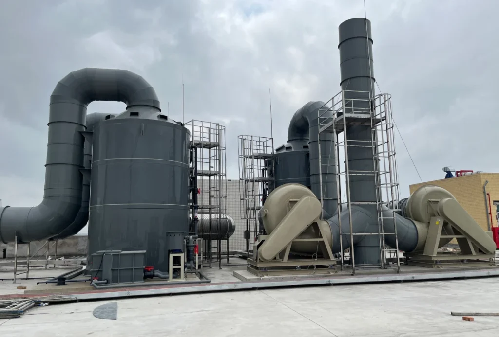
The second is the plastic industrial tank: moulded polyethylene from about 1,900 litres upward, and fabricated thermoplastics from 50 litres to more than 100,000 litres. These are the tanks a factory buys when it needs a vessel inside the building, connected to its own pipework, and sized to a duty rather than to a catalogue.
The third is the septic and waste holding tank. In the United States, “holding tank” is a term of art for a sealed vessel that receives household sewage until it is pumped out, and it is sold through agricultural and rural retailers. It is a legitimate product. It is not an industrial process water tank, and a plant that buys one for that purpose will discover the difference at the first connection.
The split matters because the standards split the same way. A municipal steel tank is designed and inspected under the waterworks standards for its material, a moulded polyethylene tank under ASTM D1998, a welded thermoplastic tank under the EN 12573 series. A specification written for one family does not transfer to another, and a supplier asked to quote against the wrong one will either decline or quietly ignore the clauses that do not apply.
The keywords that mean something else
Several of the terms that bring buyers to this subject do not mean what they appear to. “Above ground holding tank” and “above ground waste tank” return almost entirely septic tanks. “Tank reservoir” returns automotive coolant bottles and hydraulic reservoirs. “Supply tank” collides with clothing retailers and with companies whose name happens to contain the words. “Portable tank” returns folding tanks for firefighting and tow-behind tanks for recreational vehicles.
None of this is a defect in the search engine. It is a reminder that the words describe a shape and a purpose in ordinary language, and the industry has assigned narrower meanings to some of them. A buyer who orders from a result without checking which product family it belongs to can end up with a perfectly good tank that cannot do the job.
What this page is actually about
Material selection is a real question, and it has its own page. The question an industrial water storage tank has to answer is upstream of it: how much storage, in what role, fed how, drawn how. A plant that gets that wrong will specify the right polymer for the wrong volume, which is the more expensive mistake of the two.
The rest of this page works through the sizing arithmetic, the roles a tank can play, the two control problems that decide whether the tank behaves, and the three questions — waste, portability and location — that the phrase conceals.
The Tank Size Comes From the Gap, Not From the Daily Total
The most common sizing error in industrial water storage is to take the plant’s daily consumption, add a margin, and order that volume. The number that comes out is usually too large, occasionally too small, and almost never derived from anything that happens during the day.
Supply and demand are rates, not totals
A tank exists because supply and draw differ at any given moment. If a plant draws water at exactly the rate the mains delivers it, no storage is needed at all — the pipe is the system. Storage appears when the two rates diverge in time: the mains is continuous and the process is not, or the delivery is intermittent and the process is continuous, or both.
The volume required is the largest cumulative deficit. Written as an integral, it is the peak of the running difference between draw and supply. Written as arithmetic for a plant with a steady mains and a shift pattern, it is simply the rate difference multiplied by the length of the deficit period.
The peak hour sets the pipe, the deficit sets the tank
Two different numbers come out of the same draw profile, and they are frequently confused. The peak flow rate — the highest rate the process ever asks for — sets the pipe diameter, the pump, the meter and the fill valve. The cumulative deficit — the largest area between the draw curve and the supply curve — sets the tank volume.
A plant that draws 12 m³/h for ten minutes and nothing for the rest of the hour has a peak of 12 m³/h but a deficit of only 2 m³. A tank of 2 m³ covers that draw completely, provided the supply refills it before the next one. A plant that draws 12 m³/h for eight hours has the same peak and a deficit of 56 m³. The peak is identical; the two tanks are twenty-eight times apart.
Sizing a tank from the peak rate therefore overstates it whenever the peak is short, and sizing from the daily total understates it whenever the draw is concentrated. Neither number is the answer on its own.
Get the profile from a meter, not from a nameplate
Most plants know their daily consumption, because the water utility bills them for it. Very few know the shape of the day, which is the only thing that sizes a tank. A logger on the process supply recording at 15-minute intervals, run for a representative week, turns the question from an argument into arithmetic.
Where a logger is not available, the next best input is the production schedule: which lines run, when they start and stop, and what each one draws. The schedule is usually accurate enough to find the deficit, and it has the advantage of showing the shifts that the billing meter averages away.
A worked example: the two-shift plant
Take a plant with a mains connection of 5 m³/h, continuous. The process draws 12 m³/h for one eight-hour shift and nothing overnight.
The daily totals are 120 m³ supplied and 96 m³ drawn, so the plant takes in more water than it uses and a calculation based on daily volume concludes that no storage is needed. That conclusion is wrong. During the shift the tank is losing 7 m³/h, and after eight hours it has given up 56 m³. The tank must therefore hold at least 56 m³, or the process starves before the shift ends.
Overnight the arithmetic reverses: the mains delivers 80 m³ over sixteen hours, which is more than enough to refill the 56 m³ drawn during the day. The tank is sized by the 56 m³ deficit, not by the 96 m³ daily draw and not by the 120 m³ daily supply.
When no tank size can fix the arithmetic
Now run the same plant on two shifts. Demand becomes 12 m³/h for sixteen hours, or 192 m³ a day, against the same 120 m³ supplied. The deficit is 72 m³ per day and it accumulates every day. No tank volume solves this, because the problem is not timing; the supply rate is simply below the demand rate.
This is the one rule that has to be checked before any volume is calculated. Storage moves water in time. It does not create water, and a tank sized to cover a supply shortfall will run dry on a schedule set by its own volume — later than without it, but inevitably.
Intermittent supply: tanker delivery and batch fill
The same arithmetic handles deliveries. Suppose a tanker brings 60 m³ twice a day, and the process draws 12 m³/h for one eight-hour shift. Daily supply is 120 m³ against 96 m³ of demand, so the balance is positive. The tank must still bridge the interval between a delivery and the end of the shift: if the tanker arrives at the start of the shift, the tank supplies 96 − 60 = 36 m³ before the next delivery.
Batch filling from a well or a borehole works the same way. A 8 m³/h well pump running three hours delivers 24 m³ per batch; two batches a day is 48 m³. Whether that is enough depends entirely on when the process draws, which is why the delivery schedule belongs on the same drawing as the tank.
| Supply pattern | Draw pattern | Daily balance | Minimum buffer | Verdict |
|---|---|---|---|---|
| Mains 5 m³/h continuous | 12 m³/h × 8 h | +24 m³ | 56 m³ | Workable |
| Mains 5 m³/h continuous | 12 m³/h × 16 h | −72 m³ | No size works | Increase the supply rate |
| Tanker 60 m³ × 2 | 12 m³/h × 8 h | +24 m³ | 36 m³ | Workable, timing-dependent |
| Mains 5 m³/h continuous | 3 m³/h × 8 h | +96 m³ | 0 for volume | Tank only if a break is needed |
Note on the figures — these are arithmetic examples built on the stated supply and draw rates, not recommendations. The buffer column is the peak cumulative deficit, which is what sets the working volume; freeboard and the level-control band are added on top of it.
The Six Roles a Water Tank Plays in a Plant
A tank is not always just a volume. In an industrial water system the same vessel can be a hydraulic break, a process reservoir, a pump’s shock absorber, a fire reserve, a waste collection point or a thermal store. Each role has its own sizing basis, and a tank that carries two of them has to satisfy both at once.
Raw water and the break tank
The first role is the one that receives water from the supply and passes it on. Where the supply is a public main and the downstream system is not potable, or where the downstream pressure could exceed the main pressure, the tank is a break tank: a vessel with an air gap above the water line that physically separates the two systems. Its volume is set by the fill rate and the downstream draw, not by the plant’s daily consumption.
In a plant that takes municipal water and then adds a process chemical, the break tank sits between the meter and the dosing point. Its volume is often small — a few cubic metres — because its job is separation, not autonomy.
Process supply and the day tank
The second role is the day tank: a volume sized to one shift, one batch or one production run, placed close to the point of use so that the process does not depend on a long pipe run. Its volume is the consumption of the interval it serves, plus the level-control band. Day tanks are common where the water is treated or dosed after storage, because it is easier to treat a known batch than a continuous stream.
The trade-off is that a day tank carries its volume inside the building, on a floor that has to take the weight. Water at 1,000 kg/m³ means a 20 m³ day tank is 20 tonnes before the tank itself is counted, which is a structural question as much as a process one.
The buffer that stops a pump short-cycling
The third role is hydraulic rather than volumetric. A tank between a pump and its load gives the pump something to fill and the load something to draw from, so the pump can run in long cycles instead of switching on and off around a pressure set point. The volume here is small — often a few hundred litres — but it is the difference between a pump that lasts and one that wears out its contactor.
An open tank and a bladder vessel both do this job. The open tank can be inspected and cleaned; the bladder vessel is sealed and holds pressure without the pump running. Which one fits depends on whether the system needs pressure at the point of use or only a reservoir.
The fire reserve
The fourth role is a dedicated volume held for firefighting. Its size is set by the fire protection design for the site, not by the process, and it is normally kept separate from process storage so that a production draw cannot consume it. Where a single tank carries both roles, the fire volume is added to the process volume and the outlet arrangement is designed so the fire reserve cannot be drawn down in normal operation.
The usual arrangement is a fire outlet set above the process outlet, so that once the level falls past the fire connection the process can no longer draw. A vortex inhibitor on the fire outlet keeps the pump from pulling air as the reserve is used.
Waste collection
The fifth role reverses the flow. A waste tank collects a stream that cannot go to drain and holds it until it is treated or pumped out. Its volume is set by the interval between collections and the rate at which the stream arrives, which is a very different calculation from the supply-side ones above.
The sizing question is the collection interval, not the daily volume: a tank that fills in six hours has to be four times larger to last until a once-a-day collection, whatever it holds in any one hour. High-level alarms and pump-out access belong in the specification from the start, because retrofitting either into a buried tank is a project of its own.
The thermal store
The sixth role is temperature rather than volume. A tank can hold hot water or chilled water as an energy buffer, letting a boiler or a chiller run at a steady rate against a variable load. Its volume is set by the energy to be carried and the acceptable temperature swing, and its internal arrangement has to manage stratification, because hot water floats and a badly arranged tank short-circuits.
Water at 60 °C is 983.2 kg/m³ against 998.2 kg/m³ at 20 °C, so a tall tank will stratify by itself if the inlet and outlet are placed at the right heights. A diffuser at each connection spreads the incoming stream so that it does not punch through the layer it should be joining.
| Role | What sets its volume | The constraint that usually governs |
|---|---|---|
| Break tank | Fill rate and downstream draw | Air gap and overflow capacity |
| Day tank | One shift, batch or run | Level-control band and point-of-use distance |
| Pump buffer | Drawdown that limits starts | Usable volume between cut-in and cut-out |
| Fire reserve | The fire protection design | Must not be drawn by the process |
| Waste collection | Interval between collections | Segregation and pump-out access |
| Thermal store | Energy to be carried, temperature swing | Stratification and short-circuiting |
The Break Tank, and Why the Air Gap Is the Point
Break tanks are frequently specified as if they were ordinary storage vessels with an inlet and an outlet. They are not. The volume is almost incidental; the function is a physical separation between two water systems that must never mix.
What a break tank separates
Downstream of a break tank, the pressure is atmospheric. That single fact does both jobs. It stops a downstream pressure — from a pump, a pressurised process or a backflow event — from reaching the supply main, and it stops anything in the downstream system from being drawn back into the supply when the main pressure falls.
The separation is achieved by an air gap, meaning the inlet discharges above the highest possible water level rather than below it. A check valve is not an air gap. A check valve is a mechanical device that can leak, jam open or be installed backwards, and a system that relies on one has a mechanical separation rather than a physical one.
The overflow is part of the protection
An air gap only works if the water level can never rise to meet the inlet. That is the overflow’s job. An overflow sized for the maximum fill rate guarantees that a failed inlet valve spills to drain instead of pressurising the tank and closing the gap.
Two practical consequences follow. The overflow must be large enough for the fill line, not for the average flow. And it must discharge visibly — to a drain, a gully or outside the building — rather than into a closed pipe that can itself back up. An overflow that nobody can see is a protection device that nobody can verify.
Sizing the gap and the fill valve
The air gap is a distance, and it has to survive the worst case the tank can produce. The inlet must sit above the highest level the water can reach, which is the top of the overflow rather than the normal working level. Where the tank is subject to a surge — from a fast fill valve closing or from a pump downstream — the gap has to clear the surge as well.
The fill valve is the other half of the pair. A valve sized for the average demand will sit partly open for most of the day and never shut cleanly, which defeats the level control and can hide a leak. A valve sized for the maximum fill rate fills the tank in a predictable time and then closes, so a valve that fails to close shows up as an overflow rather than as a slightly high level.
Checking that the gap is still a gap
A break tank installed correctly can stop being one without anyone noticing. A length of pipe dropped into the tank to reach a lower level, a hose connected to a submerged inlet, a repair that replaces the air gap with a check valve — each of these restores the flow and removes the protection.
The inspection is therefore not a look at the tank; it is a look at the inlet. Is the discharge still above the water line? Is the overflow still open and still visible? Has anything been connected below the water line since the last inspection? Those three questions cover most of the failure modes.
Where a break tank is the wrong answer
A break tank adds a volume of water that sits at atmospheric pressure and ambient temperature, and that volume has to turn over often enough to stay fresh. Where the supply is already potable and the downstream system is the same potable system, a break tank introduces a stagnation risk in exchange for a separation that was not needed.
The same applies where the water is process water that will be treated downstream anyway: the tank is a buffer, not a barrier, and calling it a break tank invites the wrong fittings and the wrong inspection regime.
Level Control, Pump Protection and the Cost of Being Too Small
Two tanks of the same nominal volume behave completely differently depending on how the level is controlled and where the pump sits. The control band is what the plant actually uses; the nominal capacity is a shell dimension.
What the level control actually does
A float valve, a level switch or a pressure transducer sets a working band between a fill point and a draw-down point. The usable volume is that band, not the tank’s nominal capacity, and on a tall tank with a narrow band the difference can be substantial.
This is why a tank specified as “10 m³” can behave like a 6 m³ tank in service. The rest of the volume is freeboard, dead storage below the outlet, or the margin the control band never uses.
Where the sensors go
A level switch at the top and one at the bottom looks symmetrical and is usually wrong. The bottom switch has to sit above the outlet, or it reads the water in the suction pipe rather than the water in the tank, and the top switch has to sit below the overflow, or the alarm and the spill arrive together.
Two switches also fix the band by geometry. A continuous level transmitter, or a pressure sensor on a stilling well, gives a band that can be set and changed, which is what a process that varies by season actually needs. The cost difference is small against the cost of a pump that short-cycles because the band turned out to be narrower than the design assumed.
Drawdown arithmetic for an on/off pump
Where a single pump fills a tank and the process draws from it, the pump runs on and off around a pressure or level set point. The usable drawdown that limits the number of starts can be calculated directly.
In steady operation the pump adds Q − q to the tank while running and the process removes q while it is off, where Q is the pump capacity and q the draw. Taking the usual design point of q = Q/2, the run time and the off time are equal, each equal to 2ΔV/Q, so the cycle lasts 4ΔV/Q and the starts per hour are N = Q/(4ΔV). Rearranged, the drawdown is:
ΔV = Q / (4N)
For a 10 m³/h pump limited to six starts an hour, that is 10 / 24 = 0.417 m³, or about 417 litres of usable drawdown. The assumption — average draw at half the pump capacity — is stated because the answer changes with it: a process that draws a tenth of the pump capacity needs a larger buffer for the same start limit.
| Pump capacity | 4 starts/h | 6 starts/h | 10 starts/h | 12 starts/h |
|---|---|---|---|---|
| 5 m³/h | 313 L | 208 L | 125 L | 104 L |
| 10 m³/h | 625 L | 417 L | 250 L | 208 L |
| 20 m³/h | 1,250 L | 833 L | 500 L | 417 L |
| 50 m³/h | 3,125 L | 2,083 L | 1,250 L | 1,042 L |
Note on the figures — ΔV = Q/(4N) is arithmetic under the stated assumption that the average draw equals half the pump capacity. It is a sizing aid, not a pump-selection method; the pump curve, the motor’s permitted starts per hour and the control scheme all have to be checked against the manufacturer’s data.
What short cycling costs
Every start is a thermal cycle in the motor winding and a mechanical cycle in the contactor, the coupling and the check valve. A pump that starts sixty times an hour instead of six wears those parts ten times faster and heats the winding between runs that are too short to cool it.
The hydraulic cost is separate. Each start sends a pressure wave down the line, and on a long run that wave arrives at the tank as a surge. The tank that was supposed to protect the pump can end up being the thing the surge loads.
Too big is also a fault: turnover and stagnation
If the tank is sized for a rare peak rather than for the ordinary deficit, it will sit mostly full for most of the year. Turnover time — the stored volume divided by the average daily draw — becomes the number that matters, and a tank that turns over once a month is a water-quality problem regardless of what it is made of.
In the worked example above, 56 m³ against a 96 m³ daily draw is a turnover of 0.58 days — the tank refills roughly twice a day, which is healthy. The same 56 m³ tank on a process that draws 2 m³ a day would turn over once every four weeks, and the water would sit long enough to lose its residual and warm to ambient.
Two tanks instead of one
Where the volume requirement is set by a peak that happens a few times a year, a single large tank is the wrong shape for the problem. Two smaller tanks on a common header can run in series for normal duty and in parallel for the peak, which keeps the turnover short for most of the year without giving up the volume when it is needed.
The same arrangement gives maintenance a route: one tank can be drained, inspected and repaired while the other carries the plant. A single tank has to come out of service to be cleaned, which means a shutdown or a temporary vessel.
The cost is a second shell, a second set of connections and a changeover arrangement. On a plant where the peak is real and the baseline is low, that is usually cheaper than the water-quality problem a single oversized tank creates.
Stagnant water loses its chlorine residual, warms toward ambient, and supports biofilm on the wall. The design answers are to size for the real deficit rather than the worst week, to split a large requirement into two tanks that can be used alternately, or to arrange the inlet and outlet so that the tank fills and empties as a plug rather than short-circuiting between adjacent nozzles.
Waste, Portable and Fixed: Three Questions the Phrase Hides
Three further decisions sit underneath the phrase and are usually made by accident. They are worth making deliberately, because each one is expensive to reverse.
Waste streams are kept apart, not blended
A waste tank is not a smaller version of a supply tank. Its job is to hold a stream until it can be treated or removed, and the cheapest way to make that stream expensive is to mix it with another one.
Blending a small volume of a concentrated or contaminated stream into a large volume of a clean one turns the whole volume into the harder category. Keeping the streams separate at the source costs a second tank and a second pump; separating them downstream costs a treatment plant. In practice the second tank is almost always the cheaper decision.
The same argument applies to clean streams that are not identical. Rinse water from a final rinse is close to clean; rinse water from a first rinse is not. A plant that sends both to one tank has chosen to treat the average, and the average is set by the dirtier of the two.
Above ground versus below ground
An above-ground tank can be inspected, repaired and pumped out. A leak is visible, or at least it reaches a surface where it can be seen. A below-ground tank is out of the way, which is its only real advantage, and its disadvantage is that leak detection becomes a monitoring problem rather than a visual one.
For industrial water and waste, above ground is the default unless the site has no room. The phrase “above ground holding tank” in the search results usually refers to a septic tank rather than an industrial vessel, but the structural argument for keeping the tank visible applies to both.
Site access is part of the same decision. A tank that cannot be reached by the vehicle that empties it, or by the crane that set it down, is a tank that will be emptied by hand. The delivery route, the turning circle and the lifting points are worth drawing on the same sheet as the tank footprint.
Where the stored liquid is a hazardous waste, containment is a regulatory matter rather than a preference. The RCRA container standard requires a containment system able to hold 10 % of the volume of the containers or the volume of the largest container, whichever is greater, and it explicitly excludes containers that hold no free liquids from that calculation. The rule applies to hazardous waste container storage areas, not to every water tank, but the principle — contain the largest credible release — is a reasonable one anywhere.
What “portable tank” means in industry
Portability covers three quite different products. An intermediate bulk container is about 1,000 litres in a cage, moved by forklift and used as a shipping and dispensing unit. A skid-mounted tank is a vessel on a steel frame, lifted into position and connected on site. A trailer tank is a road vehicle, with the braking, lighting and load-securing requirements that implies.
Each format trades volume and wall thickness for mobility. A portable tank is generally smaller than a fixed one for the same money, because the frame, the lifting points and the transport loads all have to be paid for. And a tank that is moved has to be empty or properly baffled, which limits how much of the time it can actually be in service.
The transport loads are the part that is usually underestimated. A full IBC is about a tonne; a full skid tank of 5 m³ is five tonnes plus the frame; a trailer tank carries its own road-load case. Each of those loads reaches the shell through the frame, and the frame is where the design effort goes.
When to fix it instead
If a tank moves less than about once a year, the portability is being paid for and not used. A fixed tank with a transfer pump is cheaper, holds more for the same footprint, and can be connected permanently instead of through a hose each time.
Specifying an Industrial Water Storage Tank
The specification of an industrial water storage tank reduces to six inputs, and the first two are the ones that decide the volume. Everything after them is a constraint on the shape rather than on the size.
The six inputs
The first is the supply: the rate, and whether it is continuous, shift-patterned or delivered in batches. The second is the draw: the rate, the pattern, and the peak that the process cannot survive without.
The third is the autonomy required — the longest interval the tank must cover on its own, whether that is a shift, a delivery gap or a shutdown. The fourth is the role or roles the tank will play, because two roles add their volumes.
The fifth is the water itself: potable, raw, treated, demineralised or waste, and its temperature. The sixth is the site: footprint, headroom, access for delivery, and whether containment is required.
What each input looks like on a data sheet
The supply is a rate and a pattern: “5 m³/h from the mains, continuous, 3 bar”. The draw is a rate and a pattern: “12 m³/h for one shift, eight hours, five days”. The autonomy is a duration: “must cover a full shift if the main is shut”. The role is a word or two: break, day, buffer, fire, waste, thermal.
The water is a specification: potable to NSF/ANSI 61, or process water at 70 °C, or waste at pH 2. The site is a drawing: the footprint available, the height under the beam, the door the tank has to pass through, and whether a bund is required.
Six lines. A supplier who asks for more than these is usually asking for what follows from them — connection sizes, level control, vent — and a supplier who asks for fewer is guessing at least one of them.
The material question
Once the volume and role are fixed, the material is usually straightforward. For ambient potable water in a standard cylinder, a moulded polyethylene tank within its standard’s scope is cheaper and adequate. Fabricated polypropylene earns its place when the water is hotter than the polyethylene ceiling, when the shape has to fit a room, when the volume exceeds what can be moulded, or when the stream is process water rather than drinking water. The temperature limits, the potable certification and the freezing behaviour are set out in the polypropylene water tank article; the general material comparison is in the polypropylene tank guide.
Two constraints are worth repeating here because they affect the storage design rather than the material. A potable tank has to be certified to NSF/ANSI 61 for the shell and for every wetted component, and that standard covers health effects only — it does not cover microbial growth. And where the tank is tall or narrow, the posture itself changes the structural design, which is the subject of the vertical poly tank article.
The resin behind the shell has its own regulation. 21 CFR 177.1520 lists the olefin polymers permitted for food contact, with a density and melting-point range and an extractables limit for each; polypropylene is item 1.1a. A tank made from a compliant resin is not automatically a compliant tank, because the standard covers the resin rather than the finished article, but a tank made from a non-compliant one cannot be compliant at all.
What we build
We fabricate PP-H tanks from 5 mm to 30 mm sheet, from 50 litres to more than 100,000 litres, in vertical cylindrical, horizontal and rectangular forms, with connections welded in during fabrication. Where the duty needs a second wall, the annulus is a separate design and is covered in the double wall tank article; where the connections have to be specified, the poly tank fittings page covers the three routes through a wall.
For a quotation we need the six inputs above, plus the delivery location. Send them and the reply is a dimensioned drawing and a price. The full product range and the configuration parameters are on the PP water tanks page.
Frequently Asked Questions
How do I calculate the size of an industrial water storage tank?
Work out the largest cumulative difference between the draw rate and the supply rate. Multiply the rate difference by the length of the deficit period, then add freeboard and the level-control band. The plant’s daily consumption is not the answer unless supply and draw happen to be continuous and equal.
How long will a tank last without refilling?
Divide the usable volume by the average draw during the period the supply is off. A 56 m³ tank drawn at 12 m³/h lasts just under five hours. If that is shorter than the interval it has to cover, the tank is too small or the supply rate is too low.
Can a storage tank make up for a supply that is too small?
No. Storage shifts water in time; it does not create it. If the average supply rate is below the average demand rate over a full cycle, the tank will empty eventually regardless of its size. The fix is a larger supply, a second source or a lower demand.
What is the difference between a break tank and a storage tank?
A storage tank holds a volume for the process. A break tank creates a physical separation between two water systems, with an air gap above the water line so that downstream pressure cannot reach the supply. A tank can do both jobs, but the air gap and the overflow have to be designed in deliberately.
Should an industrial water tank be above ground or below ground?
Above ground is the default. It can be inspected and repaired, a leak is visible, and pumping out is straightforward. Below ground saves space and makes leak detection a monitoring problem rather than a visual one, so it is normally chosen only when the site has no alternative.
Is a holding tank the same as an industrial water storage tank?
Not usually. In the United States, “holding tank” most often means a sealed septic tank that receives household waste until it is pumped out. Industrial water storage is a different product with a different design basis, and the two are sold through different channels.
Sources
- ASTM International. ASTM D1998-21: Standard Specification for Polyethylene Upright Storage Tanks. Scope clauses 1.1–1.3. store.astm.org/d1998-21.html
- British Standards Institution. BS EN 12573-1:2000, Welded static non-pressurized thermoplastic tanks — General principles, and the related parts −2 (vertical cylindrical tanks), −3 (single skin rectangular tanks) and −4 (flanged joints). knowledge.bsigroup.com
- NSF International. NSF/ANSI 61: Drinking Water System Components – Health Effects, scope statement. nsf.org
- U.S. Code of Federal Regulations. 21 CFR 177.1520, Olefin polymers, table item 1.1a (polypropylene). ecfr.gov
- U.S. Code of Federal Regulations. 40 CFR 264.175, Containment, paragraph (b)(3). ecfr.gov
- The Engineering ToolBox. Water Density, Specific Weight and Thermal Expansion Coefficients. engineeringtoolbox.com
- INEOS Olefins & Polymers. Typical Engineering Properties of Polypropylene. Density, DSC melting point, Vicat softening temperature, brittleness temperature and coefficient of linear thermal expansion. ineos.com