
Key Takeaways
- The principle of operation of centrifugal fan is simple: air enters the impeller eye, the spinning blades fling it outward, and the scroll casing turns that velocity into static pressure.
- Four stages repeat in every machine — intake at the eye, acceleration through the blades, pressure recovery in the volute, and 90° discharge against the duct’s resistance.
- The velocity-to-pressure conversion in the volute is what separates a centrifugal blower from an axial fan: high pressure, not just high volume.
- The same principle of operation of centrifugal fan runs every wheel type — forward, backward-inclined, airfoil, radial — only the efficiency and dirt tolerance change.
- In FRP/PP construction the identical physics live in a molded impeller and volute with no metal in the gas path, built to survive corrosive airstreams.
How a Centrifugal Blower Works: The Principle in One Paragraph
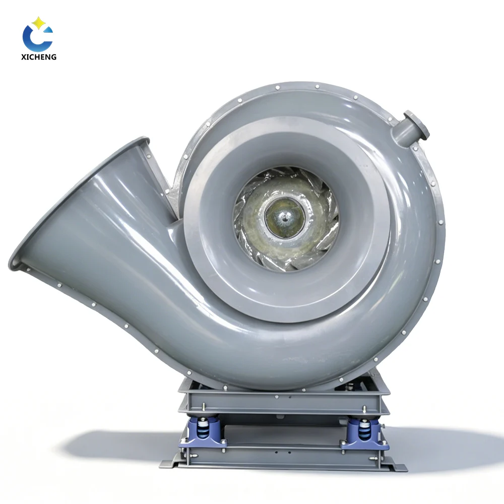
The principle of operation of centrifugal fan is the easiest machine story in ventilation. A motor spins an impeller inside a spiral scroll housing. The air enters through the impeller eye at the centre, the blades catch it and fling it outward, and the scroll casing gradually slows it down, turning the speed of the airstream into pressure that pushes against the duct. That one idea — velocity converted into static pressure — is the whole operating principle of a centrifugal blower.
This guide walks through each step of that operation, the components that carry it out, and why the principle of operation of centrifugal fan changes exactly nothing when the machine is molded in corrosion-resistant FRP or PP instead of welded steel. If you are new to the machine, our guide to what a centrifugal fan is covers the parts first, and the types of centrifugal fans guide explains how each wheel family serves a different duty. Here we stay on the physics: what happens to the air from the inlet flange to the discharge flange.
The airflow path in four moves:
- Intake — air is drawn into the eye of the impeller through the inlet cone.
- Acceleration — the rotating blades add velocity, flinging the air outward.
- Pressure recovery — the volute widens, slowing the air and building static pressure.
- Delivery — the air leaves at right angles to the inlet, ready to push through the duct.
The 90° turn is not incidental. Turning the flow lets the scroll wrap a long diffuser around a compact wheel, so a machine that fits a small floorpad still recovers useful pressure. It also decouples the inlet and discharge directions, letting a single impeller serve a dozen duct layouts. Every drawing of a centrifugal blower shows that turn, and reading it is the first step to reading the rest of the fan curve.
Step by Step: What Happens Inside the Fan
The principle of operation of centrifugal fan falls into four steps that repeat every revolution. Each one converts energy from the previous stage, and the result is a stream of air carrying usable pressure. Engineers draw the same motion as a velocity triangle — U for the blade’s own speed at the tip, Vr for the air’s speed relative to the blade, and V for the absolute velocity with which the air leaves, the vector sum of the other two. The blade angle sets how those three vectors line up, and therefore how much of the input energy becomes pressure instead of turbulence, a relationship documented in the centrifugal fan reference entry.
The whole cycle is one continuous energy conversion. The motor puts mechanical energy into the shaft; the impeller hands it to the air as kinetic energy of motion; and the volute converts that kinetic energy into static pressure, the form that does useful work against the system. Losses appear at every hand-off — friction in the bearings, turbulence at the blade edges, leakage past the tips — which is why the best fans, praised for efficiency near 84%, are the ones that minimize each one. A good impeller design moves as much of the motor’s energy to the discharge as possible; a poor one spends it on noise and heat instead.
Step 1 — Air Enters Through the Impeller Eye
Air approaches the fan straight along the shaft axis and enters through the inlet, a converging cone that accelerates the stream smoothly into the impeller eye. The spinning blades push air outward faster than it can be replaced, so a low-pressure zone forms at the centre of the wheel. That slight vacuum is what pulls the next parcel of air in, keeping the machine self-feeding. A carefully shaped inlet cone is the first efficiency decision; a poor one admits the air with turbulence that shows up as noise and wasted power.
Step 2 — The Blades Impart Velocity
Inside the wheel, each blade catches the incoming air and accelerates it through centrifugal force — the same outward pull that keeps a stone on a string when it is spun. The farther the air travels from the hub, the larger the radius and the faster its circumferential speed, so by the time it reaches the blade tips the air is moving far faster than it was at the eye. This acceleration stage of the principle of operation of centrifugal fan is the step that creates kinetic energy; the air leaves the wheel as a high-velocity stream. The blade shape decides how efficiently that happens, and it is exactly the difference between the centrifugal fan types in our companion guide.
Step 3 — The Volute Converts Velocity into Static Pressure
The high-velocity air now enters the scroll casing, a spiral passage whose cross-section grows wider toward the outlet. Widening the passage slows the air down. When a fluid slows without losing energy, its kinetic energy must convert into pressure — the same velocity-to-pressure trade a diffuser performs. The volute is precisely that: a two-dimensional diffuser wrapped all the way around the wheel. The air leaves the discharge with high static pressure and modest velocity, exactly the combination a duct system needs.
Bernoulli’s relation is the physics behind the swap: with no energy added or lost, a drop in velocity is paid for by a rise in pressure. The air that leaves an industrial radial wheel at tip speeds of tens of metres per second is slowed through the scroll until it carries enough static pressure to push through a baghouse and its duct — velocity spent on pressure, precisely as the principle demands.
Step 4 — The Air Exits at 90° Against System Resistance
Finally the air turns and leaves the casing at a right angle to the inlet axis. The static pressure it carries overcomes the resistance of filters, coils, elbows, and long duct runs; the airflow that results depends on where the fan curve meets the system resistance curve. Every pass through the machine repeats the same principle of operation of centrifugal fan, and that continuous cycle is what makes the centrifugal blower a constant-volume machine within its operating range.
Two practical notes follow from the cycle. First, the fan’s airflow is set by the intersection of the fan curve and the system curve — raise the system resistance, and the operating point slides to less flow at higher pressure. Second, because the eye must stay fed, the inlet side needs an unobstructed straight approach; a tight elbow right at the inlet starves the eye and reduces what the wheel can deliver. Duct practice follows the physics, not the other way around.
Inside the Machine: Centrifugal Blower Components
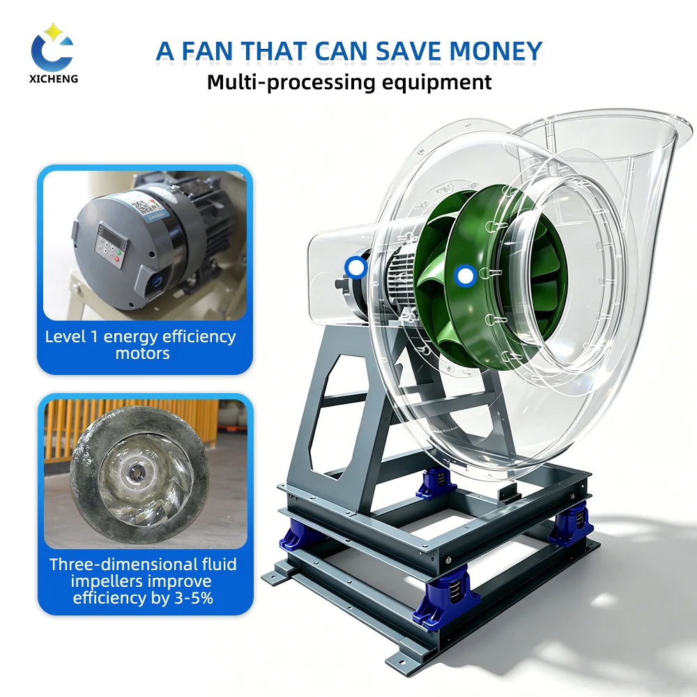
Every blower that obeys the principle of operation of centrifugal fan is the same set of parts sized to the duty. The table lists each component with the job it performs in the operating cycle.
| Component | Job in the operating cycle |
|---|---|
| Impeller (fan wheel) | Adds velocity to the air; blade geometry sets volume, pressure, and efficiency |
| Inlet cone | Smooths axial air entry into the eye, minimizing turbulence losses |
| Volute / scroll casing | Widening spiral passage that converts velocity into static pressure |
| Motor | Supplies the turning power, direct-coupled or through a belt drive |
| Shaft and bearings | Carry the impeller and its radial and axial loads, keep rotation smooth |
| Base and housing | Support the assembly and align the drive; legs or plinth as the routing needs |
The Impeller (Fan Wheel) Design
The fan impeller is the heart of the machine because it is the only part that delivers energy to the air. Blades are fixed to a back plate or between two shrouds and joined to a hub on the shaft. The impeller design choice — how many blades, at what angle, whether curved or flat — fixes the fan’s pressure, flow, efficiency, and how much dirt it can carry. In a molded FRP impeller, the blade profile and the hub are one continuous piece, which removes the welded joints that crack and corrode in chemical service.
Selection of the wheel material follows the same logic as the casing. Steel wheels suit clean dry air at temperature; stainless carries moisture and mild corrosives; molded composite covers the acid and solvent chemistries where every other metal becomes the weak point. The blade geometry is fixed by the airstream’s duty — dust, no dust, pressure, volume — and the material is then chosen so that geometry survives the air that carries it.
Direct Drive vs Belt-Driven
Direct drive mounts the impeller on the motor shaft: few parts, no loss through a transmission, and the lowest maintenance, which suits continuous duty. Belt-driven blowers run a V-belt between the motor and the fan shaft, letting the designer change impeller speed by changing pulley sizes and letting the buyer tune flow for a variable-air-volume system. The belt also shields the motor from some mechanical shock and extends its life, at the cost of belt inspections and a small efficiency loss.
Motor Speed, Poles, and the Fan Laws
Impeller speed is set by the motor and its poles. An AC motor’s speed follows roughly RPM = 120 × frequency ÷ pole count, so a two-pole motor on 60 Hz turns near 3,600 RPM and a four-pole near 1,800 RPM. Speed matters out of proportion because of the fan laws: airflow changes linearly with speed, but pressure changes with the square and power with the cube. A ten-percent speed cut reduces power draw by roughly a third — the whole reason variable-frequency drives pay for themselves on continuous blowers. The fan engineering guide from Air Control Industries walks the same relationships in detail.
Bearing and Shaft Arrangement
The shaft carries the impeller between its bearings, and the bearing layout fixes how the fan handles load and where maintenance lands. Small fans mount the impeller between two pillow blocks on a base; larger and hotter-duty fans favor an outboard bearing at each side of a long shaft to keep the wheel clear of the motor and its heat. Belt-driven machines carry the extra load of belt tension, so the fan-side bearings are chosen heavier. Grease fittings, vibration sensor ports, and a drain for condensed moisture are the details that decide whether a blower runs for years or fails at the first unscheduled shutdown.
Why Centrifugal Fans Build Pressure and Axial Fans Don’t
Both machines spin an impeller, but they convert energy differently, and that is why a centrifugal blower can operate against high resistance while an axial fan cannot. An axial fan pushes air straight along the shaft, adding a small pressure rise with each blade pass; it excels at moving large volume in open or lightly loaded systems. A centrifugal fan turns the airflow through the impeller and then against the volute, and in doing so converts the air’s velocity into static pressure — the working principle of operation of centrifugal fan stated in one contrast.
| Property | Centrifugal blower | Axial fan |
|---|---|---|
| Airflow direction | In axially, out at 90° | Straight through the axis |
| Static pressure ability | High — resists long duct, coils, filters | Low — best in open flow |
| Volume capacity | Medium to high | Very high per size |
| Efficiency at high resistance | Holds up through the duct | Drops sharply with resistance |
| Typical duty | Dust collection, fume exhaust, process pressure | Ventilation, cooling, condenser flow |
The pressure difference also shows up in the fan laws: for a given machine, airflow varies with speed, pressure with the square of speed, and fan power with the cube of speed. Because the centrifugal wheel concentrates most of that energy into pressure rather than raw velocity, it can push air through scrubbers, baghouses, and long industrialized duct — the reason almost every scrubber and pollution-control train is driven by a centrifugal blower rather than an axial prop.
A worked example makes the fan laws concrete. If a blower runs at 1,800 RPM and the speed drops to 1,620 RPM — a 10% cut — airflow falls by 10%, pressure by roughly 19% (0.9²), and power by roughly 27% (0.9³). The same 10% speed cut therefore trims a quarter of the electricity bill on a continuously running fan, which is why variable-frequency drives and belt-pulley changes are the first levers an energy engineer pulls. Matching speed to demand rather than throttling with a damper is the single largest operating-cost decision a fan owner makes.
The two families are complementary, not rivals. If a system offers little resistance and wants large volume — a low-pressure laboratory hood exhaust or a condenser cooling row — an axial fan moves it cheaply. The moment filters, elbows, packed towers, or long runs enter the picture, the centrifugal blower becomes the reliable choice because it is the one with static pressure to spare. Most pollution-control systems are a stack of such resistances, which is exactly why the machine in the fan room is centrifugal.
The Same Principle Runs Every Wheel Type
Whatever impeller you pick, the principle of operation of centrifugal fan is identical — intake at the eye, acceleration through the blades, pressure recovery in the volute. What changes is how well each wheel performs each stage, and the type table from our types of centrifugal fans guide applies directly to the physics here.
| Wheel family | Blade geometry | Effect on the operating cycle | Static efficiency |
|---|---|---|---|
| Forward-curved | Many short blades curling with rotation | High volume from a small diameter, faster wheel speed | up to 65% |
| Backward-inclined | Few longer blades leaning against rotation | Low turbulence, best energy conversion, non-overloading | 80–90% |
| Backward-curved | Curved plates against rotation | Same lean, tolerant of light dust and moisture | up to 84% |
| Airfoil | Hollow wing-profile blades | Cleanest flow, quietest, most efficient — clean air only | up to 84% |
| Radial | Straight flat blades, radial to hub | Self-cleaning, high pressure, lower efficiency | 50–70% |
| Radial-tip | Backward blade with a radial tip | Middle ground for semi-abrasive streams | up to 78% |
Efficiency is the direct measure of how cleanly the wheel performs the two energy conversions in the cycle: velocity gained in the blades, pressure recovered in the volute. The most efficient wheels — backward-inclined and airfoil — spend the least energy on turbulence, which is why they dominate continuous industrial duty. The U.S. Department of Energy fan system sourcebook documents the same pressure-conversion physics from the energy-audit side.
The blade count itself is part of the design language. Forward-curved wheels carry many thin blades — forty or more on some small wheels — because each blade does only a little work and the crowd of them keeps flow smooth at low pressure. Backward-inclined and airfoil wheels carry far fewer blades, typically eight to sixteen, each one large and tilted to do more work per pass with less skin friction. The volute cannot fix a mismatched blade set; it can only recover whatever pressure the wheel produced. Reading the blade count and angle on a catalog drawing tells you the family and the efficiency to expect before you open the performance table.
Nothing about the operating principle changes with construction material. The same wheel geometry sees the same velocity triangle whether the blades are steel or molded composite; what the material changes is the air the fan is allowed to handle, which the corrosion section covers next.
Design Details That Change the Operating Point
Tip Clearance and Housing Geometry
The clearance between the blade tips and the volute wall is tiny in a well-built centrifugal fan — commonly around a quarter of a percent of the impeller diameter. Reducing the clearance raises peak pressure because less high-velocity air leaks back from the discharge side to the low-pressure eye; increasing it wastes that same flow. The spiral of the volute is not decorative: its gradually widening cross-section manages the velocity-to-pressure conversion and keeps the air attached to the casing instead of peeling into turbulence. Framed in the scroll housing, this spiral is the reason buyers ask for a scroll fan or a snail fan and mean the same centrifugal machine.
A related geometry choice is the cutwater, the point where the volute tongue begins. Its position and clearance set the low-flow behaviour of the fan: get it wrong and the fan surges or howls at low volume. Together, tip clearance, the cutwater, and the rate at which the scroll widens are the three numbers a designer adjusts to hit a target pressure curve.
Static vs Dynamic Pressure
Understanding the operating point starts with separating the two pressures the fan creates. Static pressure is the push that overcomes system resistance — the part an engineer sizes for. Dynamic pressure belongs to the air’s velocity and turns back into static pressure when the flow slows. A centrifugal blower is most valuable where system resistance is high and static pressure dominates; a stream built only from velocity would stall inside the duct. Every blade and casing choice is a decision about which of the two pressures to maximize, and the principle of operation of centrifugal fan is the tool that makes the trade predictable.
Overloading vs Non-Overloading Power Curves
The same cycle also fixes how a fan behaves when the system opens up. Forward-curved, radial, and radial-tip wheels keep drawing more power toward free delivery — the overloading types — while backward-inclined and airfoil wheels peak mid-range and then fall, protecting their own motor. That distinction, detailed in the fan-curve explainer in the types guide, is a direct consequence of blade geometry interacting with the same pressure conversion, and it decides how much motor margin your system needs.
The Same Principle, Built for Corrosive Air (FRP/PP)
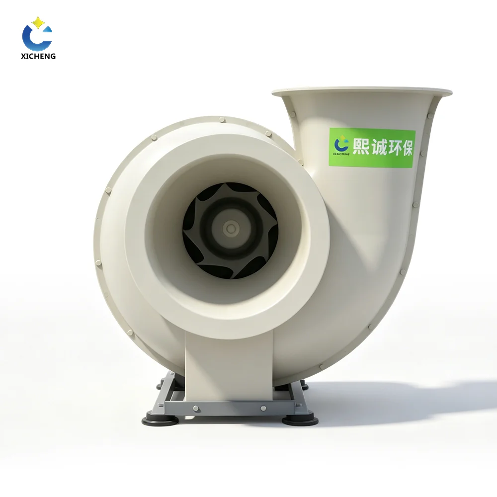
A steel centrifugal fan obeys the principle of operation of centrifugal fan perfectly right up until the chemistry fails it. Wet, acid, chlorinated, or solvent-laden air attacks the scroll and the impeller, pits the welds, and unbalances the wheel. The engineering answer is to keep every part of the gas path plastic. An FRP or PP centrifugal blower molds the impeller, the volute, and the inlet cone from the same corrosion-resistant material, so no metal ever touches the stream — the identical velocity-to-pressure physics, in a material that sheds the chemistry instead of fighting it.
Choose FRP blowers for the hottest, most aggressive gas (to roughly 250 °F) and PP blowers for moderate temperatures at lower first cost. The molded one-piece construction also holds dynamic balance longer than a welded assembly because there are no joints left to corrode. With the same operational principles in composite, the product lines at XICHENG FRP blowers and XICHENG PP blowers span the wheel families; the full FRP/PP blower range covers sizing and options.
Maintenance on a composite blower follows the same physics with two material twists. First, inspect the impeller and volute for wear on schedule — a molded composite part is smooth, so it resists dust build-up better than riveted steel, but the balance still needs a check after any mechanical cleaning. Second, never ignore the fasteners between the plastic casing and the metal motor frame: isolating gaskets and corrosion-coated bolts keep the two material worlds from fighting each other, and they are a standard option on XICHENG FRP and PP builds.
Centrifugal Fan Working Principle FAQ
What is the working principle of a centrifugal fan?
Air enters the impeller eye axially, the rotating blades throw it outward by centrifugal force, and the widening volute casing converts that velocity into static pressure before the air exits at 90° to the inlet. The principle of operation of centrifugal fan is the same four steps in every machine: intake, acceleration, pressure recovery, delivery.
Why does a centrifugal blower make more pressure than an axial fan?
Because the centrifugal wheel turns the airflow and then decelerates it in the volute, converting the air’s kinetic energy into static pressure. Axial fans push air straight through and never slow it in a diffuser, so they move volume but cannot hold pressure against long or restricted ducting.
Which part of a centrifugal blower creates the pressure?
The volute — the spiral scroll casing — is the pressure creator. The impeller only gives the air velocity; the widening scroll takes that velocity and trades it for static pressure, just as a diffuser would. Engineers call this the pressure-recovery stage, and its efficiency decides most of the blower’s overall efficiency.
What does the velocity triangle mean for fan design?
The velocity triangle relates the blade’s own tip speed (U), the air’s speed relative to the blade (Vr), and the absolute velocity leaving the impeller (V). Fan design uses those three vectors to set blade angles so that kinetic energy is delivered to the airstream with the least turbulence, which shows up directly as efficiency.
Direct drive or belt drive — which is better?
Direct drive is simpler and lower maintenance for continuous duty; belt drive permits speed changes and reduces the reflected load on the motor. Choose belt drive when you expect to tune the airflow or need to extend motor life, and direct drive when uptime and simplicity are the priority.
Can the same working principle handle corrosive gases and dust?
Yes. The physics are identical; the material is what must differ. For abrasive dust, choose the radial wheel family, which is self-cleaning. For wet or acid gas, build the same principle of operation of centrifugal fan in FRP or PP so that no metal ever contacts the stream.
Get a Quote for Your Centrifugal Blower
Every XICHENG blower applies the same principle of operation of centrifugal fan to your process: give us the airstream content, the CFM, the static pressure, and the temperature, and our engineers will match the wheel and the FRP or PP material to the duty. We will confirm the operating point against your fan curve and quote the drive, the bearings, and the corrosion-resistant build.
Tell us about your application and we will recommend the machine that fits. Contact XICHENG for a quote or a second opinion on your specs.
