
Key Takeaways
A competent activated carbon adsorption box design starts from five inputs: airflow, pollutant and concentration, outlet target, run time, and process conditions. Every part of the box follows from those numbers, never the reverse.
Face velocity — airflow divided by bed face area — is the first number you set. Keep it in the 0.3–0.5 m/s band: any faster robs contact time and raises pressure drop, any slower builds a box nobody wants to pay for.
Size the carbon charge with working capacity, roughly 10–20% of carbon weight, not the saturation figure on the data sheet. Equilibrium capacity is what the isotherm claims; working capacity is what the bed actually holds before the outlet limit is touched.
Empty bed contact time of 2–4 seconds below about 1,000 ppm is the design rule of thumb, and bed depth is what delivers it. Airflow gives you face area; the outlet target gives you the depth that buys time against breakthrough.
Before you compare quotations, run your own numbers so a spec table can be checked instead of trusted: divide airflow by filtration area to verify face velocity, confirm the carbon charge and its CTC, and ask for a Certificate of Analysis with the shipment.
Designing a Box That Meets Its Number, Not a Drawing
Every underperforming extraction system this industry has ever built has the same origin: a box that was sketched to fit a footprint instead of a box that was calculated to fit an airflow. If you are here to put an activated carbon adsorption box design on a desk and ask a supplier to build it, the good news is that the method is small. Five numbers decide the whole vessel, and this guide runs through each one in the order a designer would use them, then closes with a full worked example and a way to sanity-check the quotation that comes back.
The five inputs are the design airflow, the pollutant and its inlet concentration, the outlet target your permit allows, the run time you need between change-outs, and the process conditions that reach the vessel: temperature, humidity, and dust. Feed those in, and face area, media grade, bed depth, carbon mass, and pretreatment all fall out. Nothing else changes the drawing.
This article is the sizing half of the series. The companion guide on this site covers the complete activated carbon adsorption box — what it removes, how it is built, and how to install and operate it safely — and the mechanism article explains the pore structure and breakthrough behavior behind every number used here. When you are ready for the hardware, a factory-built activated carbon box realizes exactly the geometry the activated carbon adsorption box design produces.
The Five Inputs Every Activated Carbon Adsorption Box Design Starts With
Five inputs is not a simplification; it is the definition of an activated carbon adsorption box design. Each one is measured or chosen once, feeds exactly one decision, and the decisions chain together in a fixed order. Table 1 lines them up with the piece of the box each one controls.
Table 1. The five design inputs and what each one determines
| Design input | What it decides | Design step |
|---|---|---|
| Design airflow Q (m³/h) | Face area, duct size, fan selection | Step 1 |
| Pollutant identity and inlet concentration | Media grade (CTC), isotherm loading | Step 2 |
| Outlet target (permit limit) | Bed depth and empty bed contact time | Step 3 |
| Run time between change-outs | Carbon volume and series-bed layout | Step 4 |
| Temperature, humidity, dust | Pretreatment, materials of construction, safety margins | Step 5 |
Keep this table on your desk. Every supplier question that sounds technical — what flow rate, what outlet, what media — is really asking for a row in Table 1, and every answer you give moves the design one step forward.
Step 1 — Airflow Sets the Face Area
Step 1 of an activated carbon adsorption box design is airflow, because airflow fixes the single most visible dimension of the vessel: the face area the gas sees when it enters the bed.
The 0.3–0.5 m/s Face Velocity Band
Face velocity is airflow divided by bed face area, and sound design keeps it in the 0.3 to 0.5 m/s band for granular and pellet carbon. Below the band the box — and the fan with it — becomes oversized; above it, contact time shortens, pressure drop climbs, and the risk of channeling through low-density pockets rises. The face velocity is the first check a competent designer performs on any quotation, which is why it returns later in this article.
The arithmetic is one division. A 6,000 m³/h stream is 1.67 m³/s; at a chosen 0.4 m/s, that demands a little over 4 m² of face area. A field box that carries the same airflow on 2 m² is running at 0.8 m/s and will struggle to hold contact time, whatever its brochure claims.
Face Area, Not Box Volume, Comes First
Notice the order: face area first, volume later. Many buyers quote cubic meters of carbon before they know the face area, but the two are linked through the bed depth, and the depth is fixed by the outlet target, not by an arbitrary proportion. Face area from airflow now; bed volume in Step 3; carbon mass in Step 4.
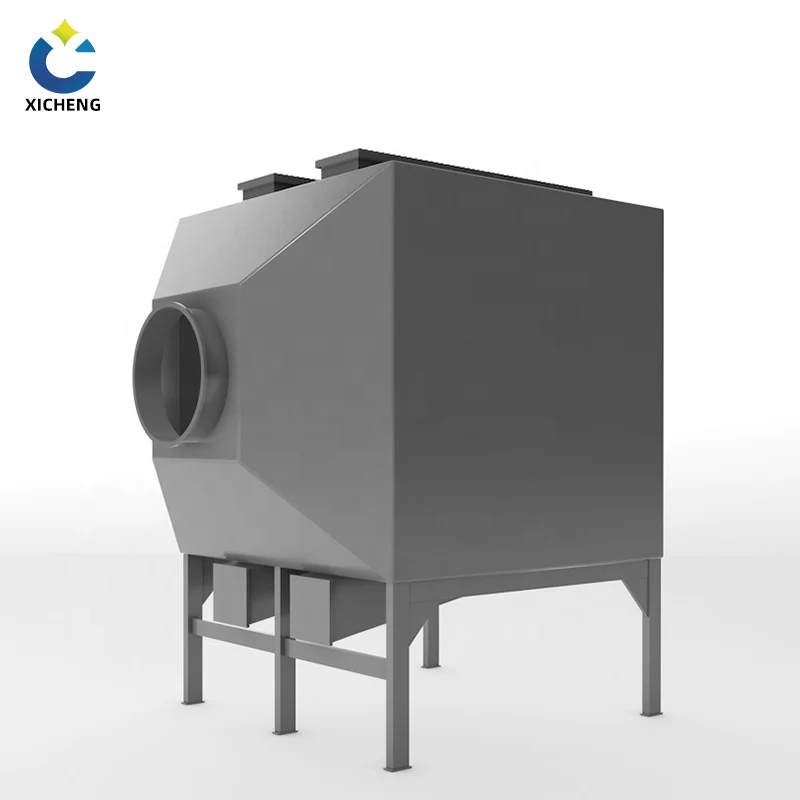
The face area also fixes the fan. A deeper bed raises the static pressure the blower must overcome, so the polypropylene blowers for the system are selected on both flow and differential pressure, not on flow alone.
Step 2 — Pollutant and Concentration Pick the Media
Step 2 of an activated carbon adsorption box design matches the carbon to what is in the gas. The pollutant’s molecular weight and volatility decide the pore structure that will hold it, and the concentration decides the loading the bed can actually reach in service.
CTC Is the Gas-Phase Number, Iodine Is Not
For air duty the specification that matters is CTC activity, the percentage of carbon tetrachloride vapor adsorbed by weight, because it measures gas-phase capacity directly. Coal-based granular carbon typically quotes CTC in the 50 to 80 percent range, coconut shell 55 to 70 percent, and honeycomb media 30 to 50 percent, which is why honeycomb suits high-volume, low-concentration work rather than heavy solvent load. Iodine value is a fine QC figure for water-phase micropores, but choosing a gas-phase media on iodine alone is how undersized beds happen.
A second rule: heavier, higher-boiling molecules adsorb better. Toluene and xylene are captured readily; methane and carbon monoxide pass through a carbon bed untouched. If your pollutant sits below roughly 50 molecular weight, carbon adsorption is the wrong tool, and the closing section of this guide applies instead.
Work With Working Capacity, Not Saturation
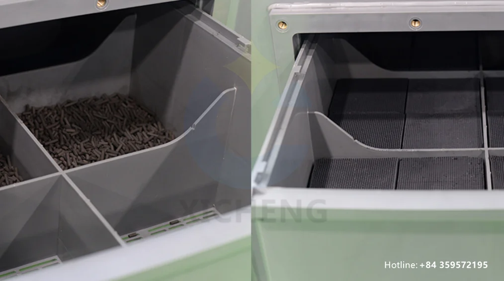
Data sheets quote equilibrium capacity, the amount a fresh laboratory sample holds at ideal isotherm conditions. Real beds cannot use all of it, because the outlet limit is reached while the rear of the bed is still clean. The number to size with is working capacity, roughly 10 to 20 kilograms of pollutant per 100 kilograms of carbon, and the engineering reference on this point is Process Engineering’s Adsorption on Activated Carbon — Part 1, which sets the working basis directly.
Note one more penalty from the same source: a conditioned bed that has cycled several times may hold only about half of what virgin carbon absorbed, because pollutant molecules lodge in micropores and struggle to leave. Plants that regenerate media should account for that drop, or the change-out interval quietly halves.
Step 3 — Outlet Target Sets Bed Depth and Residence Time
Step 3 is where an activated carbon adsorption box design earns its outlet number. Airflow delivered a face area; now the outlet concentration your permit allows decides how deep the bed must be, through a quantity called empty bed contact time.
EBCT: The Time the Gas Spends in the Bed
Empty bed contact time is the bed volume divided by the volumetric flow, expressed in seconds, and it is the standard shorthand for how long each gas packet spends near the carbon. For VOC service below roughly 1,000 ppm, design EBCT commonly runs 2 to 4 seconds; heavy or high-boiling loads sit at the lower end, and demanding outlet limits at the high end. The 6,000 m³/h stream from Step 1 is 1.67 m³/s, so a bed one meter deep on a 4 m² face holds 4 m³ of media and lands at an EBCT near 2.4 seconds.
Two suppliers can quote the same airflow and deliver very different EBCT. The difference is usually a shorter bed quoted to win a price, and it shows up as a steeper breakthrough curve. The carbon adsorber guidance maintained by the U.S. EPA documents the monitoring practice that keeps such a bed legal, the operating side of the same number.
Why Bed Depth Controls Breakthrough
Depth is the variable that buys time. A longer bed holds the mass transfer zone entirely inside the carbon, so the outlet stays clean while the front of the bed loads; a shallow bed pushes the zone toward the outlet early, leaving a thin slice of carbon doing all the work while the rest sits idle. The mechanism article on this site explains the mass transfer zone and the breakthrough curve in detail — the shape of that curve is really what decided your bed depth, and the activated carbon adsorption working principle guide gets into the details.
Step 4 — Run Time Sets the Carbon Charge and Change-Out
Step 4 turns the bed into an operating cost. Once face area and depth are fixed, the design question becomes how much carbon the vessel must hold so the change-out interval matches your production schedule — the purchase decision inside every activated carbon adsorption box design.
Working Capacity in Real Units
Keep working capacity in the units that make the arithmetic honest: kilograms of pollutant per kilogram of carbon. A 15 percent working capacity means each 1,000 kilograms of media holds 150 kilograms of pollutant before the outlet limit is reached. If the vendor hands over only a saturation figure, ask for the working value; it is the number that decides real service life.
The Loading Equation: mass = C × Q × t ÷ WC
The whole of Step 4 is one equation. Pollutant load over a run is concentration times flow times hours; divide by working capacity and you have the carbon mass. Feed the paint-shop numbers — 190 mg/m³ inlet, 6,000 m³/h, forty run-hours a week — and the bed takes in about 1.13 kilograms of pollutant every hour. A 2,000 kilogram charge at 15 percent working capacity holds 300 kilograms, or roughly 265 operating hours, before the outlet climbs. That landing point is your change-out.
The equation also shows the levers. Double the run time and the carbon charge doubles; halve the inlet concentration and the same bed lasts twice as long. When a plant reports a legally built box that never lasts between holidays, it usually means this equation was solved with a saturation number instead of a working one.
Series Beds and the 500-Hour Question
For streams that must never stop, two beds in series — lead-lag — let you change out the lead bed while the lag bed keeps treating. In a simple box the practical alternative is a generous change-out schedule. A useful floor for low-humidity indoor duty is replacement around 500 operating hours or every three months, whichever comes first, and then outlet monitoring refines the interval from real data. Change out more often than the calculation says and you are replacing early; less often, and you are betting the outlet number.
The hardware behind that schedule is straightforward. An activated carbon filter box in the right size is simply the Step 1 and Step 4 numbers welded together — face area, depth, and a charge drawn from the loading equation.
Step 5 — Process Conditions Decide Pretreatment and Materials
Step 5 protects the design from the gas stream itself. The last input an activated carbon adsorption box design carries is the condition of the air at the flange: temperature, humidity, dust and aerosols, and how close the mixture sits to its flammability limit.
Temperature, Humidity, and the Risk of Bedfire
Adsorption favors cool, dry gas. Capacity slides as temperature rises — the difference between 20 °C and 50 °C is visible in the isotherms for a common monomer — so plan to cool the feed below 40 °C before the bed. Relative humidity over roughly 50 percent lets water compete for the same micropores, and above 70 percent the loss is significant; dry, cool, and drain condensate first. The activated carbon filter design guidance published by Jacobi and used across the industry treats these limits as fixed inputs and supplies the reference numbers summarized here.
Heat is the second hazard. Adsorption releases heat, and a warm, concentrated stream can run away toward a bedfire. Two design habits cover it: keep the inlet concentration below about 25 percent of the lower explosive limit, and never let the face velocity fall below roughly 0.1 m/s where hotspot risk exists, because the moving air is what carries heat out of the bed. The safety story for the installed box, including change-out precautions, is in the activated carbon adsorption box guide hosted on this site.
Dust and Aerosols Damage the Bed
Solids and droplets are silent killers of carbon beds. Dust above about 1 mg per normal cubic metre blinds the outer surface and drives up the pressure drop; oil or water mist wets the pores and blocks them entirely. A simple prefilter ahead of the box and a coalescer or demister for known mist streams cost little and protect the charge. Where the stream is corrosive, spec the vessel material accordingly — in a polypropylene fabricator the wetted parts are born resistant, which is one reason activated carbon boxes shipped in this material travel into paint and food plants without complaint.
The external reference on these conditions is Jacobi’s design and selection guide for activated carbon air and gas filters, which walks through temperature, humidity, linear velocity, and the 25 percent LEL rule in one place.
Worked Example: Sizing a Box for a Paint Shop Exhaust
A design method is only worth its numbers. Table 2 runs the whole activated carbon adsorption box design for a single paint line: 6,000 m³/h of booth exhaust carrying mixed solvents near 50 ppm, an outlet target of 30 mg/m³ total VOC, and a change-out the production manager wants to see every few weeks rather than every few days.
Table 2. The full sizing runsheet for a 6,000 m³/h paint-shop box
| Step | Parameter | Value | How it is set |
|---|---|---|---|
| Input | Design airflow Q | 6,000 m³/h = 1.67 m³/s | Measured at the booth, plus margin |
| Input | Pollutants | Toluene and mixed paint solvents | MSDS and lab list |
| Input | Inlet concentration | ≈ 190 mg/m³ (~50 ppm) | Hood measurement |
| Input | Outlet target | ≤ 30 mg/m³ total VOC | Permit / plant standard |
| Step 1 | Face velocity | 0.42 m/s | Chosen inside the 0.3–0.5 m/s band |
| Step 1 | Face area A = Q ÷ v | 4.0 m² | 1.67 ÷ 0.42 |
| Step 3 | Empty bed contact time | ≈ 2.4 s | Chosen inside the 2–4 s band |
| Step 3 | Bed volume V = EBCT × Q | 4.0 m³ | 2.4 × 1.67 |
| Step 3 | Bed depth = V ÷ A | 1.0 m | 4.0 ÷ 4.0 |
| Step 4 | Carbon mass at 500 kg/m³ | 2,000 kg | Bulk density × volume |
| Step 4 | Pollutant flux C × Q | ≈ 1.13 kg/h | 190 mg/m³ × 6,000 m³/h |
| Step 4 | Working capacity | 15% by weight | Vendor data, conditioned basis |
| Step 4 | Pollutant per charge | 300 kg | 2,000 × 0.15 |
| Step 4 | Change-out at 40 h/week | ≈ 265 h ≈ 6–7 weeks | 300 ÷ 1.13 |
Read the table top to bottom and it is a recipe. Airflow speaks first and chooses its own face area; the outlet target then adds a bed depth that holds enough contact time; media and working capacity turn that volume into a carbon mass; and the mass, divided by the load the gas actually brings, returns the change-out. If the paint line added a second booth, the airflow doubles, the box doubles — the method does not change, only the inputs.
Notice where the design is forgiving and where it is not. Drop the inlet to 100 mg/m³ and the same bed lasts twice as long; rise toward 1,000 ppm and it is spent in days, which is the signal that the box has left its lane and a concentrator, a solvent-recovery train, or a scrubber belongs upstream. If the change-out policy tightens to every month, either the run hours fall or the carbon charge rises. Cross-checking a quotation against a runsheet like this one is the fastest way to use an activated carbon adsorption box design.
How to Read a Supplier’s Activated Carbon Box Spec Table
A quotation normally arrives as a spec table: model, handling airflow, filtration area, carbon amount, dimensions, weight. Read cold, those rows look like facts. Read with the design method in hand, each row becomes a claim you can check. The fastest way to use an activated carbon adsorption box design, in other words, is backwards — run it against the supplier’s table.
Verify Face Velocity First
Divide the quoted airflow by the quoted filtration area. A table that lists 5,000 m³/h on a 2.8 m² face runs at about 0.5 m/s, and 10,000 m³/h on a 5.2 m² face at about 0.53 m/s — both inside the band. When the division returns 0.8 m/s or more, the box is relying on short contact time and dense media, and it is worth asking the vendor why before you buy. The carbon weight per airflow tells the same story: 300 kg paired with 2,000 m³/h is a serious charge, while 300 kg paired with 8,000 m³/h is a thin veneer of carbon over a large empty shell. Compare like for like — the grade’s CTC and bulk density, not just its kilogram number.
The Seven Numbers a Supplier Needs From You
Design works in both directions. If you hand a factory the seven numbers below, an activated carbon box or a full activated carbon filter box comes back sized to your data, and you can verify the table with the checks above. The list is short enough to write in one email.
-
Design airflow in m³/h, and how you measured it.
-
The pollutants, with molecular weight or boiling point.
-
Inlet concentration, including its range across shifts.
-
The outlet limit, or the permit number that sets it.
-
Run hours per week and the change-out interval you can accept.
-
Gas temperature and relative humidity at the box flange.
-
Dust and mist load, plus the footprint and access available for change-out.
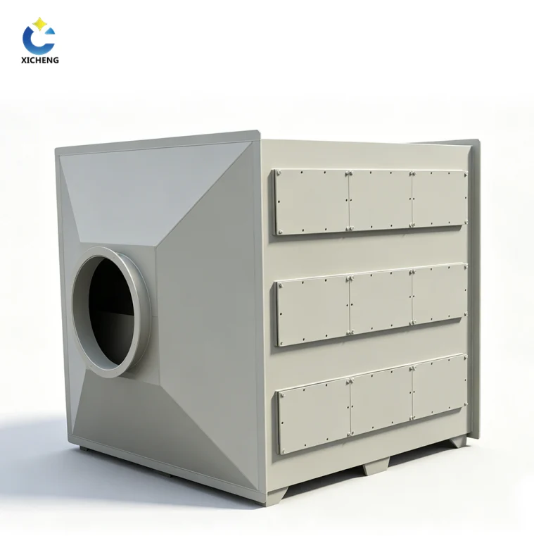
Most quotations fail for a reason that has nothing to do with steel. The industrial activated carbon filter and the activated carbon adsorption equipment lines on this site are quoted from exactly these inputs, and the supplier drawing should show the face area, the bed depth, and the media grade on the same sheet as the price.
When a Box Stops Being the Right Answer
An activated carbon adsorption box design has a lane. High volume at low concentration, solvent-heavy streams, and inorganic gases each point to a different machine, and choosing the machine first is cheaper than wrestling a box into the wrong job.
Above roughly 1,000 m³/h at concentrations in the tens of parts per million, a rotary concentrator wheel loads carbon and concentrates the pollutant into a stream one-tenth the size, then sends that small hot stream to a thermal oxidizer. The carbon is still doing the capture, but a wheel, not a box, is the vessel that makes the economics work.
If the solvent is worth money and arrives above roughly 500 ppm, recovery becomes a profit line, and a regenerable twin-bed adsorber — or the taller activated carbon adsorption tower at high flow — earns more than it costs. For those duties the tower product family is the direct next step, and the same two design steps apply with a vessel that holds more contact time.
Acid gas, ammonia, and water-soluble inorganics are the wet scrubber’s territory, not carbon’s, and wet scrubber trains handle them at any load. Where a stream mixes acids with VOCs, a scrubber ahead of the carbon box protects the expensive media and extends its life; the two technologies are partners, not rivals.
Activated Carbon Box Design FAQ
What size activated carbon adsorption box design do I need?
Size from four numbers. Airflow sets the face area at 0.3–0.5 m/s, the outlet target sets the bed depth at 2–4 seconds of empty bed contact time, and the run time plus working capacity set the carbon mass. Worked through, a 6,000 m³/h paint booth lands near 4 m² of face area and a 2,000 kg charge.
How do I calculate the activated carbon fill volume?
Bed volume is empty bed contact time times flow. At 2.4 seconds and 1.67 m³/s, that is 4 m³; the weight is the volume times the media bulk density, about 500 kg/m³ for granular carbon. Verify that the resulting charge holds the expected pollutant load before the change-out.
What face velocity should a carbon adsorber run at?
0.3 to 0.5 m/s for granular and pellet carbon is the working band. Compact boxes run a little warmer, near 0.5 m/s, and where bedfire risk exists the velocity should never fall below about 0.1 m/s.
How long does a carbon bed last before change-out?
Until the outlet concentration approaches your limit. A simple low-load box is commonly replaced around 500 operating hours or every three months, then the interval is refined from monitoring. The loading equation gives the honest answer for your own concentration and run hours.
Why is my outlet concentration rising even though the carbon is fresh?
Check the three usual suspects. Humidity above 50 to 70 percent occupies the pores; an inlet much higher than the design figure loads the bed faster than planned; and a sudden pressure-drop fall signals channeling, where gas bypasses the bed through a crack. Fix the condition, not the box.
Do I need a wet scrubber or an activated carbon box?
Organic vapors are carbon’s job; acid gases, ammonia, and water-soluble inorganics are the scrubber’s. For mixed streams, put the scrubber upstream so it protects the carbon, and the pair passes any permit.
