
Key Takeaways
Activated carbon does not absorb gases; it adsorbs them. Pollutant molecules are held on the internal surface of the carbon by weak physical forces, which is why understanding how activated carbon adsorption works is the first step in designing any carbon filter system.
Pore size distribution matters more than total surface area. Small VOC molecules enter micropores; larger molecules and color bodies need mesopores. A high BET number tells you nothing about where the surface area is.
Iodine value is a quick micropore check, but for air and VOC duty the spec that matters is CTC activity. Never choose carbon from iodine value alone.
The breakthrough curve is the honest schedule for a carbon bed. Watch outlet concentration and differential pressure, and act when the leading edge of the mass transfer zone reaches the outlet.
Spent media can be thermally regenerated at 700–900 °C to recover 85–95% of capacity, losing 5–15% per cycle. Plan change-out as a consumable cost, not a repair.
What Is Activated Carbon Adsorption?
Activated carbon adsorption is the process by which gases and vapors are removed from an airstream by being held on the surface of porous carbon. The carbon is processed, or activated, to open millions of tiny pores that add up to a surface area far larger than the exterior of the particle suggests. When a gas molecule touches that surface, weak electrical forces keep it there.
This mechanism is the engine inside the equipment this site sells. If you are evaluating an activated carbon adsorption box, the box is only a housing; the work is done by the mechanism described here. Knowing how activated carbon adsorption works at the molecular level is what separates a system that runs for months on a carbon charge from one that breaks through in weeks.
Adsorption vs Absorption
Both words describe taking a substance out of a gas or liquid, but they happen differently. In absorption, the incoming substance is drawn into the volume of the material, the way a sponge soaks up water. The sponge’s molecular structure does not change; the water simply fills gaps inside it.
In adsorption, the incoming molecules stick to the surface of the material. They do not enter the carbon particle itself. Activated carbon works by adsorption: the contaminant attaches to the carbon surface in the pores. That single difference explains why carbon can bind gases without swelling or dissolving, and why it releases them again under the right conditions.
Physical Adsorption vs Chemisorption
Adsorption itself comes in two forms. Physical adsorption (physisorption) is attraction by van der Waals forces, the same weak intermolecular attraction that holds molecules together in a liquid. No chemical bond is formed, the pollutant’s molecular structure stays intact, and the process can be reversed by heat. This is the mechanism behind ordinary activated carbon used in air filters.
Chemisorption forms an actual chemical bond between the contaminant and the carbon, or a treated carbon surface. It is stronger than physisorption and harder to reverse, and it is deliberately engineered for pollutants that plain carbon holds poorly, such as hydrogen sulfide using impregnated media. When a supplier recommends a special grade, they are usually asking you to switch from physisorption duty to chemisorption duty.
The practical consequence is simple: adsorptive capacity is real, but it depends on matching the mechanism to the contaminant. The next sections explain the geometry that makes carbon work, then the indicators that tell you a batch of carbon is up to the job.
Why Activated Carbon Is a Strong Adsorbent
Activated carbon’s power comes from geometry, not chemistry. A single gram of high-quality coconut-shell carbon can carry roughly 1,000 to 1,200 square meters of internal surface, an area comparable to four tennis courts. The trade press likes to point out that a teaspoon of carbon has more surface area than a football field, and the comparison is essentially accurate. Framing how activated carbon adsorption works around the three pore classes below makes the rest of the specification sheet easy to follow.
Pore Structure: Micro, Meso, and Macro Pores
That surface exists inside a network of pores, and the pores are classified by diameter because diameter decides what gets trapped:
Micropores (below 2 nm) are the primary adsorption sites. Small molecules such as VOCs, chlorine, and taste-and-odor compounds fit into them, which is why micropore volume drives most gas-phase work. In our context, the VOCs in paint and printing exhaust are small molecules that belong in micropores.
Mesopores (2–50 nm) act as transport channels into the particle and also adsorb larger molecules, including color bodies and dyes. A carbon rich in mesopores is good at decolorization but holds small gas molecules less efficiently.
Macropores (above 50 nm) are the access highways. They carry the airstream toward the interior pores and matter mainly for kinetics; they hold little contaminant on their own.
Surface Area vs Pore Size Distribution
Total surface area is the headline number, but it is not the whole story. What matters is where that area sits. A wood-based carbon can post a higher BET surface area than a coconut-shell carbon and still be worse at capturing small VOCs, simply because its area is concentrated in mesopores rather than micropores.
BET Surface Area
BET (Brunauer–Emmett–Teller) surface area is measured by nitrogen adsorption at 77 K and reports the total area across all pore sizes. Typical values run 800–1,200 m²/g for steam-activated coconut-shell carbon, 800–1,100 for coal-based, and 1,200–1,800 for chemically activated wood carbon. Specialty super-activated carbons can reach 2,000–3,000 m²/g.
Why Pore Size Distribution Matters More
Two carbons can post identical BET numbers and perform completely differently on the same airstream, because one carries micropores and the other carries mesopores. For solvent and odor duty the micropore fraction does the work. So when a supplier leads with BET, ask for the pore size distribution as well; BET describes how much surface exists, and the distribution describes whether it is usable for your contaminant.
For a fuller account of how carbon is made and what its feedstock options are, the Water Tech Online primer on activated carbon adsorption covers feedstock, forms, and the way pore structure varies between wood, coal, and coconut sources.
The Adsorption Process, Step by Step
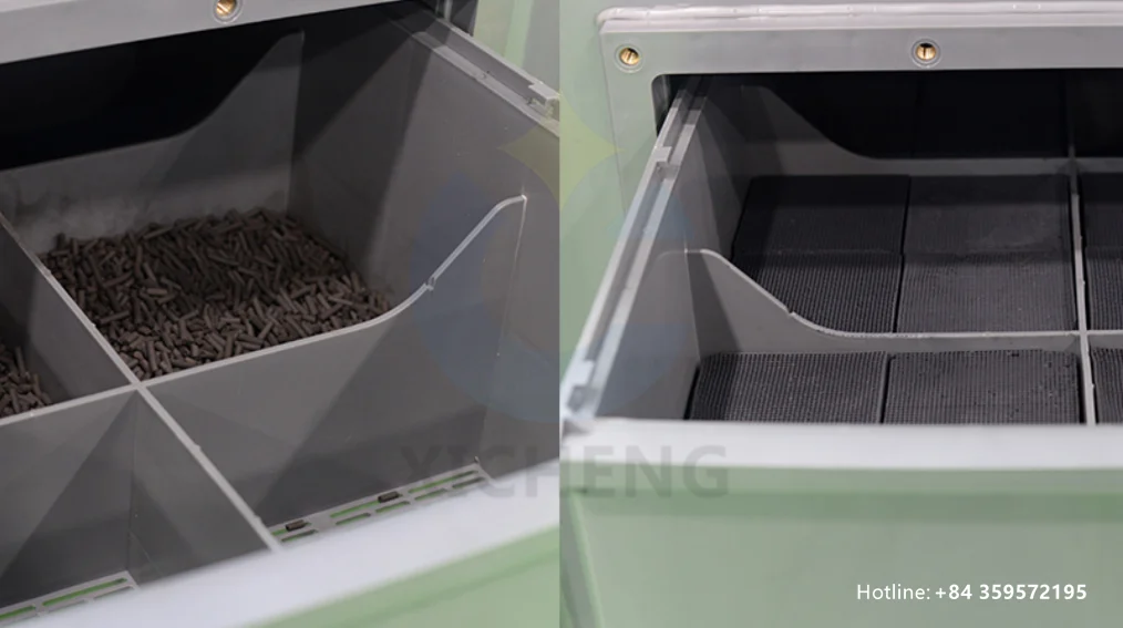
Once the geometry is in place, how activated carbon adsorption works becomes a matter of getting the pollutant molecule from the free airstream to a waiting adsorption site inside the particle. Three steps happen for every molecule, in order, and each one can become a bottleneck. Figure 1 shows the packed bed in which these steps happen.
Step 1: Transport into the Carbon Particle
The contaminant must first reach the interior surface, and reaching it is a diffusion problem, not a chemistry problem.
Film Diffusion
At the outside of each carbon granule sits a thin, almost stagnant boundary layer of air. The pollutant has to cross this film by diffusion. Fast airflow thins the film and helps, but the mass transfer that counts happens across this barrier; it is one reason fan selection and face velocity show up in carbon system design.
Pore Diffusion
Once inside the particle opening, the molecule travels through macropores and mesopores toward the micropores where it will be held. This inward travel is pore diffusion. Deep, tortuous pores slow it down, which is why the same carbon can work well for one contaminant and slowly for another. Kinetics, not just capacity, decide practical performance.
Step 2: Attraction at the Adsorption Site
At a vacant micropore the molecule is caught by van der Waals forces. Individually these forces are weak, but a carbon pore offers many nearby carbon atoms, and the combined attraction is enough to hold a small organic molecule for hours or weeks. The site is now occupied: it can hold no more, and the number of open sites is what turns fresh carbon into spent carbon. This is the exact point where the engineering guides on activated carbon describe uptake as an equilibrium, not a one-way trap.
Step 3: The Mass Transfer Zone in a Packed Bed
In a real bed the contaminant does not load evenly. At the start, the inlet face of the bed adsorbs everything and the outlet air is clean. As the inlet carbon saturates, the active region, called the mass transfer zone (MTZ), moves downstream through the bed. The carbon ahead of the zone is still fresh; the carbon behind it is spent. This moving boundary is the heart of how activated carbon adsorption works in a packed vessel: it turns fresh carbon into spent carbon one zone at a time.
The MTZ has a finite length, set by how strongly the carbon holds the contaminant, the airflow, and the bed layout. When the leading edge of the zone reaches the outlet face, the outlet concentration starts to climb. That moment, not the calendar, is the honest signal that the media is done, which is the subject of the breakthrough curve in a later section.
What Activated Carbon Adsorption Catches Best
Not every pollutant is adsorbable, and knowing the boundary is worth as much as understanding how activated carbon adsorption works. The practical window for activated carbon adsorption follows the size and volatility of the molecule, not its toxicity.
The Molecular Weight Window (Roughly 50–200)
Physisorption is most efficient for organic vapors with molecular weights between about 50 and 200. In practice that covers nearly every solvent a factory exhausts: toluene, xylene, methanol, ethyl acetate, methyl ethyl ketone, isopropanol, styrene, and the mixtures found in paint booths, printing presses, and adhesive lines. It also covers the low-level organic compounds that make up most industrial odors, which is why carbon is the default final stage for odor control.
Molecules in this window diffuse into micropores, are held long enough to bring outlet concentrations down, and accumulate until the pores fill. Heavier members of the solvent family adsorb more strongly than light ones, which is why beds that handle toluene saturate differently from beds that handle methanol.
What It Does Not Remove
Three classes of material defeat an activated carbon bed, and each requires a different answer:
Permanent gases. Carbon monoxide, carbon dioxide, and methane are too small and too weakly held to stay on the surface at normal temperatures. They pass straight through a bed, so carbon is not the tool for inert-gas scrubbing.
Heavy, sticky organics. High-boiling materials such as tars and resin fume do not desorb cleanly and can polymerize on the carbon, coating the pores and poisoning the bed. They need to be knocked out upstream, not fed to the media.
Particles. Adsorption works on molecules, not solids. Dust loads the outer surface of the bed, raises pressure drop, and blocks access to the micropores. Solids belong in a pre-filter or HEPA stage before the carbon, a combination covered by the activated carbon adsorption box guide referenced earlier.
Carbon Quality: Iodine Value, CTC, and BET
Once you understand how activated carbon adsorption works, the next question is whether the carbon you are buying is actually good at it. Suppliers quote several numbers on a data sheet, and each one measures a different part of the adsorption story. Table 1 summarizes the four specs you will see most often.
Table 1. Activated carbon quality metrics and what each one tells you
| Metric | What it measures | Probe molecule | Test standard | Most relevant for |
|---|---|---|---|---|
| Iodine value | Micropore capacity, small molecules | Iodine, ~0.27 nm | ASTM D4607 | Water treatment, general QC, small-molecule organics |
| CTC activity | Total pore volume in gas phase | Carbon tetrachloride vapor | ASTM D3467 | Air purification, VOC removal, solvent recovery |
| BET surface area | Total surface area + pore size distribution | Nitrogen at 77 K | ASTM D6556 | R&D, comparing carbons, detailed characterization |
| Methylene blue value | Mesopore and macropore capacity | Dye, ~1.2 nm | Varies | Decolorization, large molecules, wastewater |
Iodine Value and Micropores
Iodine value is the number most quoted in the industry: the milligrams of iodine adsorbed per gram of carbon. Because iodine is a small molecule, the value tracks micropore volume. High-iodine carbon (1,000–1,200+ mg/g) is the standard for gas-phase and solvent duty; the 800–1,000 range suits general water and air work; below about 500–800 the carbon is a decolorization grade and a poor choice for VOC capture.
Treat iodine value as a first check, not a verdict. It is a single-point measurement, and two carbons with the same iodine value can differ in pore size distribution and surface chemistry.
CTC for Gas-Phase Service
For air and VOC treatment the spec that matters is CTC activity: the percentage of carbon tetrachloride vapor a carbon sample can adsorb, by weight. Typical grades run 40–50% for general odor control, 50–60% for VOC removal and solvent recovery, and 60–80% for high-concentration vapor duty. When a supplier quotes CTC for an air application, they are speaking the right language.
BET and Pore Size Distribution
BET provides the full surface-area picture and, more usefully, a pore size distribution curve. Request BET when you are comparing carbons from different raw materials or when a single number is not explaining why two candidates behave differently.
Which Spec to Ask For
Apply the simple rule: water duty is an iodine question, air duty is a CTC question. For the exhaust systems this site builds, ask for CTC activity (at least 50% for VOC streams), hardness, mesh size, moisture, and ash, and request a Certificate of Analysis with each shipment. When you specify an industrial activated carbon filter or box charge, the media data sheet should carry exactly these numbers so you can compare one supplier’s carbon against another’s.
The Breakthrough Curve: When a Bed Is Spent
Laboratory capacity numbers are best-case values. In service, an activated carbon box uses only the portion of capacity that is available before the outlet limit is touched, the working capacity. The U.S. EPA guidance on carbon adsorbers puts a common working value near 10 to 20 kg of pollutant per 100 kg of carbon, a fraction of the theoretical uptake. The shape that determines this working value is the breakthrough curve, which is how activated carbon adsorption works expressed as an operating limit.
Reading the Curve
Plot outlet concentration against time or volume treated, and a fresh bed traces a flat line near zero. As the mass transfer zone reaches the outlet, the line bends upward, then climbs steeply as more of the bed saturates. The curve looks like an S: flat, rising, flat. The point where the outlet reading crosses your allowed limit is breakthrough, and it marks the moment the media should be changed under your permit, not at theoretical saturation.
The bed is never evenly loaded. Table 2 describes the three zones that exist inside a packed bed at any moment, which is why sampling only at the outlet, or only at the inlet, tells you little.
Table 2. The three zones of a working carbon bed
| Bed zone | Carbon state | What it means | Typical plant action |
|---|---|---|---|
| Inlet zone | Saturated | Holds contaminant at inlet concentration | Change-out trigger once zone reaches outlet |
| Working zone (MTZ) | Partly loaded | Active uptake happening here | Sample top/middle/bottom to locate it |
| Outlet zone | Fresh | Clean carbon ready to work | Safety margin until breakthrough |
Monitoring Outlet Concentration and Pressure Drop
Two measurements run a carbon bed in practice. Outlet concentration, from a portable detector or periodic lab sample, tracks the breakthrough curve directly; the reading trending toward your limit is the warning. Differential pressure across the bed tracks the mechanical condition: a steady climb means dust loading, and a sudden drop usually means channeling, a crack in the bed that lets gas bypass the carbon entirely.
The EPA materials referenced in this article describe these monitoring indicators for carbon adsorbers in detail, and the carbon adsorber control-technique page is a sound reference for both the breakthrough concept and the monitoring practice that keeps a bed legal.
Real-Service Factors: Temperature, Humidity, Concentration
The mechanics above describe how activated carbon adsorption works under ideal conditions. Real plant air is warmer, wetter, and more concentrated than a laboratory sample, and every deviation moves the working capacity. Designers who skip this section pay for it in premature change-outs.
Temperature and Exothermic Adsorption
Adsorption releases heat. Because it is exothermic, lower temperatures favor more uptake and higher temperatures reduce it. A rule of thumb in the industry: a 10 °C rise in gas temperature can cut working capacity by 5 to 15%. The practical consequences run both ways. Keep the inlet gas cool to protect capacity, and treat sudden heat as a warning, because high concentration feeding a low airflow raises bed temperature and, at the extreme, creates a fire risk that the safety notes on an activated carbon adsorption box call out.
Humidity Above About 50% RH Cuts Capacity
Water molecules are small, and they compete with pollutant molecules for the same micropores. Above roughly 50% relative humidity, that competition becomes measurable and gas-phase capacity drops noticeably. In borderline climates the fix is not a bigger box but a drier feed: pre-filter and cool the stream, drain condensed water before the bed, or choose a hydrophobic impregnant where the process allows. A carbon box fed cold humid air will appear undersized no matter how much media you pack in.
Concentration and Contact Time (EBCT)
Higher inlet concentration pushes more mass onto each gram of carbon, which looks good on a load curve but also drives the bed to breakthrough faster, because the MTZ advances more quickly. Contact time sets how much of the bed the gas actually reaches. Too little time, and the gas leaves before the carbon reaches equilibrium, wasting the tail of the bed. In gas-phase systems the design works from an empty bed contact time, keeping the flow slow enough and the bed deep enough that the mass transfer zone fits inside the vessel. These three factors, temperature, humidity, and concentration, are the reason media manufacturers quote working capacity, not saturation capacity, and the reason a carbon system is sized on process data rather than on a lab sheet.
Media Replacement: When and How
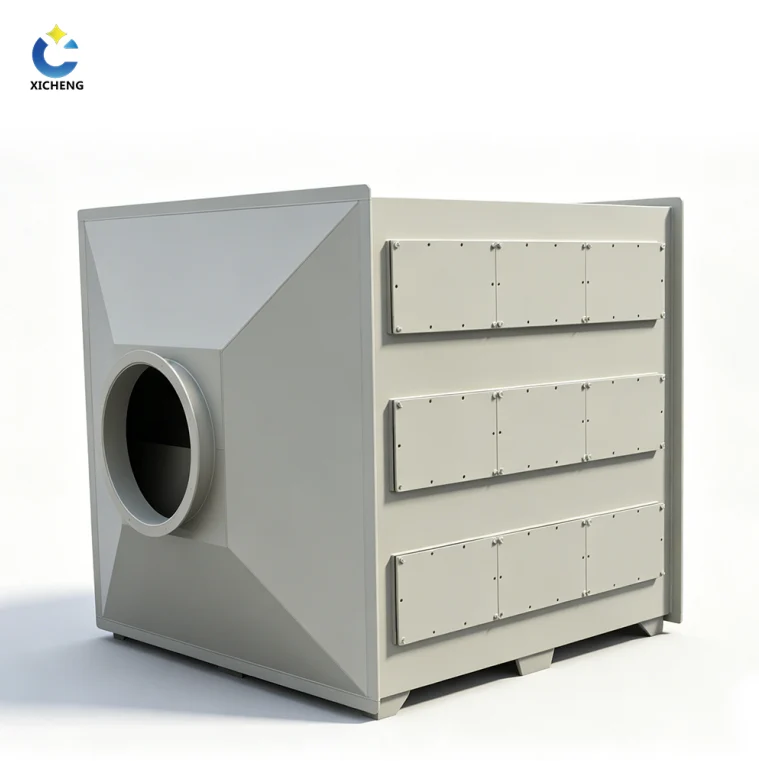
Carbon is a consumable. The pores fill, the working capacity drops, and the media has to come out. This section completes how activated carbon adsorption works in practice, because it explains where the spent material goes and what replacement costs in operation. Figure 2 shows the kind of internals through which the change happens on a packaged unit.
Virgin vs Reactivated Media
Spent carbon does not have to be new carbon. Two options exist, and the choice is an economic one based on how many times the media can survive the round trip.
Thermal Regeneration at 700–900 °C
Off-site regeneration heats the spent carbon in steam or an inert atmosphere, turning the furnace to drive adsorbed pollutants off the surface. The process restores roughly 85 to 95% of virgin capacity, and reactivated carbon typically costs about half of fresh material. Air and solvent carriers are the ones that tolerate this cycle well; a bed poisoned by tars or metals often cannot be revived economically.
Capacity Loss per Cycle
Every cycle costs something. Regeneration degrades the pore structure slightly, and capacity falls 5 to 15% per cycle, so after a handful of regenerations the media is better replaced with fresh carbon. The trade press compares the economics in the activated carbon basics primer; the net rule is simple, calculate virgin versus reactivated cost at your change-out frequency, and treat whichever you choose as a planned consumable item.
Planning the Change-Out
Change-out should be scheduled from data, not from a fixed calendar. Use the breakthrough curve and the differential pressure trend to forecast a change month, then reserve the carbon in advance so the swap does not stall production. On units with a single bed the box goes out of service during the swap; on twin units the lead-and-lag arrangement lets the lag bed carry the load while the lead bed is recharged, which is why plants on continuous duty often buy the media exchange as part of the activated carbon filter box supply contract.
Safety takes priority in the change itself. Spent carbon can hold the exact pollutants it removed, so treat it as contaminated, wear gloves and respiratory protection, and never enter an empty vessel without an atmospheric test, because wet carbon consumes oxygen. Plan the access, the bags, and the waste paperwork before the first scoop.
From Mechanism to Equipment: The Activated Carbon Adsorption Box
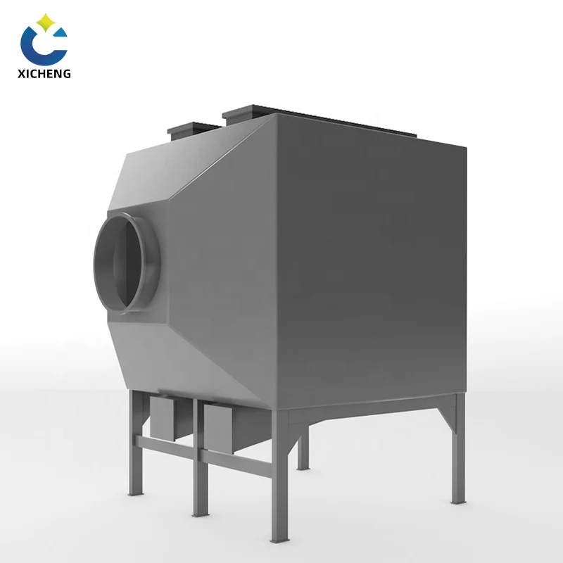
Everything in this article compresses into one engineering question: what does how activated carbon adsorption works say about the hardware you install? The answer is that the mechanism decides the geometry, and the geometry is exactly what a box builder translates into steel. Figure 3 shows where it all lands.
How the Mechanism Maps to the Box
Take the three steps of the adsorption process and each one names a box design parameter. Transport needs low face velocity and a bed deep enough to hold contact time. Attraction needs the right micropore grade, chosen from the iodine and CTC figures in Table 1. The mass transfer zone needs enough bed length to keep the zone inside the vessel between change-outs. A packaged activated carbon box is simply a factory-built realization of those three requirements, with flanges, an access hatch, and the carbon charged at the ratings the mechanism allows.
The full operating and safety story for that equipment, including heat-of-adsorption precautions and change-out procedures, is in the activated carbon adsorption box guide on this site. The design calculation that turns airflow into bed depth is the subject of a separate design guide in this series; here the point is that every design decision in that guide flows from the mechanism described above.
Media and Sizing: What a Supplier Needs
To translate mechanism into a quotation, a competent supplier needs four numbers: design airflow, the pollutant and its concentration, the required outlet concentration, and the run time you can tolerate between change-outs. From these they select the carbon grade, the bed dimensions, and the change schedule. Custom activated carbon adsorption equipment is quoted exactly this way, and high-volume plants find the vertical activated carbon adsorption tower the more efficient vessel for the same mechanism at large flow.
Give a supplier your real process data rather than a rounded airflow, because the mechanism punishes approximations. Temperature, humidity, and concentration from the previous section enter the calculation directly, and a truthful data sheet is what separates a six-month media life from a ten-week disappointment.
FAQ: How Activated Carbon Adsorption Works
Does activated carbon adsorption work on all gases?
No. It is efficient for organic vapors in roughly the 50 to 200 molecular weight range, which covers industrial solvents and odors. Permanent gases such as carbon monoxide and methane pass through, and heavy tars can poison the bed. Check the molecular weight and vapor pressure of your pollutant before sizing carbon.
What is a good iodine value for activated carbon air filters?
For air and VOC duty, ask for 800–1,000 mg/g as a solid standard, and for demanding solvent service a high-micropore grade in the 1,000–1,200+ range. For gas-phase systems, pair the iodine figure with a CTC activity of at least 50%, because CTC is the better predictor of vapor adsorption.
How long does activated carbon adsorption continue to work before change-out?
There is no fixed answer; the bed runs until the breakthrough curve shows the outlet concentration at your limit. Plants commonly plan six to twelve months on average solvent loads, but the honest schedule always comes from monitoring, not from a calendar.
Does high humidity stop activated carbon adsorption from working?
Not completely, but water competes with pollutant for the same pores. Above roughly 50% relative humidity, gas-phase capacity drops noticeably. Dry and cool the feed, drain condensate before the bed, and account for the loss in sizing when the stream is consistently wet.
Can spent carbon from an adsorption system be regenerated?
Yes. Thermal regeneration at 700–900 °C restores 85–95% of capacity and typically costs about half of fresh carbon, but each cycle costs 5–15% of capacity. After a few cycles the media is better replaced with virgin carbon.
How do I know an activated carbon adsorption box needs fresh media?
Watch the two numbers this article describes. Outlet concentration trending toward your permit limit is breakthrough, and a steadily climbing differential pressure is dust load. Act on either and the box keeps running; ignore it and treatment quietly stops.
