A chemical fume exhaust duct is not a general exhaust duct with a better material. It is a duct system built to carry a stream that is corrosive, frequently condensable and sometimes acutely toxic, and the codes that govern it, the velocities it needs, the liquid it produces and the pressure it has to hold are all different from ordinary ventilation. This guide works through that system layer: what the hazardous-exhaust code actually forces, how to set the velocity from the contaminant rather than from habit, how to manage the condensate that forms inside the duct, when a wash-down is required, and how the whole chain — hood, duct, scrubber, fan, stack — has to be arranged. Material selection still matters, but on a chemical fume exhaust duct it is the second decision, not the first.
Key Takeaways
- A chemical fume exhaust duct is a hazardous exhaust system, not ordinary ventilation. It is governed by the hazardous-exhaust provisions of the mechanical code (IMC 509), which impose rules general exhaust ductwork never has to meet — incompatible materials cannot share a duct, perchloric acid can never be manifolded, and fire and smoke dampers are prohibited inside the duct.
- Nonmetallic duct for corrosive fumes has to pass a fire test. The code requires a flame-spread index of 25 or less and a smoke-developed index of 50 or less. Standard polypropylene fails this; flame-retardant PP and rigid PVC are the listed options.
- Velocity is set by the contaminant, not by a single number. Vapors and gases run at an economic optimum of roughly 1,000–2,000 fpm (5.1–10.2 m/s); heavier fume and particulate need more. Too slow and the stream drops out inside the duct; too fast and fan power rises with the cube of velocity.
- Condensation, not the material datasheet, decides whether the duct lasts. A scrubbed, saturated gas cooling from 45 °C to 25 °C releases about 0.042 kg of liquid per cubic metre — roughly 85 L/h at 2,000 m³/h. That liquid has to drain, and a horizontal run with no fall is where acid exhaust fails.
- The duct runs under negative pressure and the fan sits downstream. Hazardous exhaust is drawn, not pushed, so a leak pulls air in rather than pushing fumes out, and placing the fan after the scrubber keeps it out of the corrosive stream.
- Material is a routing decision, not an argument. Acid mist, hydrofluoric acid, solvents and perchloric acid each route to a different duct material, and the routing follows chemistry, not price.
What Makes a Chemical Fume Exhaust Duct Different
Start with what the duct carries. A general exhaust duct moves air, or air with a little dust; a chemical fume exhaust duct moves a process stream that will attack the duct wall, and the design has to assume that attack is continuous rather than occasional. The stream arrives as a vapor, a fume, a mist or a gas, and the qualitative character of what it carries — acid, base, solvent or oil — is what drives every downstream decision about material, velocity, drainage and joints. Treating the duct as a passive tube is the single most common reason a chemical fume exhaust duct fails inside two or three years.
Three Failure Modes: Corrosion, Dissolution, Melting
A duct wall under a chemical fume fails in one of three ways, and knowing which one applies tells you what the material has to resist. Corrosion destroys a metal by chemical or electrochemical action — it is the reason an uncoated or cut-edge steel duct fails first at welds, flanges and scratches. Dissolution attacks plastics and coatings by dissolving the surface, and melting softens or destroys a plastic or coating through prolonged high temperature. The two plastic-side failures matter because they are silent: a coating that dissolves or a thermoplastic that softens exposes whatever is underneath, and if the substrate is metal, corrosion then begins from the inside.
The practical consequence is that the same aggressive stream can defeat a material for different reasons at different points in its life. A solvent attacks a coating that an acid would not touch; an acid attacks a metal that a solvent would leave alone; a hot stream melts a liner that would be inert cold. This is why a chemical fume exhaust duct cannot be specified from a single “corrosion-resistant” label — the specification has to name the primary corrosive element and the operating temperature together.
Why “General Exhaust” Rules Do Not Apply
Ordinary exhaust ductwork is governed by rules written for air: seal the joints, support the weight, move the volume. A chemical fume exhaust duct sits under a different set of rules, because the stream can be flammable, toxic or both. The mechanical code defines a hazardous exhaust system as one that captures and conveys hazardous emissions — flammable vapors, gases, fumes, mists or dusts, and airborne materials posing a health hazard such as toxic or corrosive substances — and it applies whenever a flammable contaminant can reach 25 percent of its lower flammability limit, a health-hazard rating of 4 is present at any concentration, or a rating of 1–3 is present above 1 percent of the lethal concentration. See the hazardous-exhaust provisions of the International Mechanical Code, Section 509.
Once a duct falls inside that definition, the rules change in ways a general exhaust designer will not expect: incompatible materials may not be conveyed in the same duct, fire and smoke dampers are banned, nonmetallic duct must pass a flame-and-smoke test, and the whole run has to stay under negative pressure. Those are the subject of the next section, and they are the reason a chemical fume exhaust duct is a different product class from a comfort-ventilation duct of the same diameter.
The Code Layer: IMC 509 and What It Forces
The hazardous-exhaust section of the mechanical code is short, but almost every clause changes a design decision. Four of them matter most for a duct carrying chemical fume, and each one is a trap for a designer who has only worked on general exhaust. The four are: what may share a duct, how perchloric acid must be handled, what may be installed inside the duct, and what a nonmetallic duct has to prove.
Incompatible Materials Cannot Share a Duct
The code states that incompatible materials, as defined in the fire code, shall not be exhausted through the same hazardous exhaust system. In practice this means that two fume streams that can react — an acid and a base, an oxidizer and a solvent, anything that could form a hazardous product on contact — have to be kept in separate ducts rather than merged into one manifold. The clause exists because a manifold is a mixing chamber: two streams that are individually manageable can become a fire, a toxic gas release or an explosive mixture once they meet inside the duct.
The same section adds that a hazardous exhaust system shall not share a common shaft with other duct systems, except where both are hazardous exhaust systems originating in the same fire area. Where the streams are genuinely compatible, the code does allow them to be manifolded — but only under a set of conditions, which is where the next point comes in.
Perchloric Acid Is Never Manifolded
The code’s laboratory exception permits several fume streams to be combined, but it carves out one absolute prohibition: perchloric acid hoods and their connected exhaust shall not be manifolded. Perchloric acid is not merely corrosive; heated or concentrated it forms perchlorate salts and organic peroxides that are shock-sensitive and explosive, and a shared manifold would let those residues collect in a duct carrying other chemistry. The consequence is a dedicated, single-purpose run from the hood to the discharge point.
The standards stack up behind that rule. NFPA 45 requires that perchloric acid heated above ambient temperature be used only in a chemical fume hood specifically designed for it (see NFPA 45), and ANSI/AIHA Z9.5 requires a dedicated perchloric hood above 85 percent concentration. The duct that serves it is a special case in every respect — it takes the shortest path outdoors, avoids horizontal runs, and is washed down. The flame and smoke behaviour of the duct material itself is covered in our flame retardant PP duct guide.
Fire and Smoke Dampers Are Prohibited
In ordinary ductwork a fire damper is a safety feature. In a hazardous exhaust duct it is forbidden: the code states that fire dampers and smoke dampers are prohibited in hazardous exhaust ducts. The reason is that a damper is a moving obstruction in a stream that may be flammable — closing it can trap an explosive mixture or a hot gas behind the blade, and a damper that sticks partly open leaves a stream that is neither safely open nor safely closed. The same logic drives the rule that a hazardous exhaust duct must run directly to the exterior of the building and may not pass through other ducts or plenums.
For the designer this removes an option they may have assumed: you cannot route a chemical fume exhaust duct through a shared plenum and rely on a damper at the fire separation. The duct has to reach the outside on its own, and fire separation is handled by enclosure, not by a damper inside the duct.
Nonmetallic Duct: FSI 25 / SDI 50
Where a duct carries nonflammable corrosive fumes or vapors, the code permits a nonmetallic duct — but only if the material exhibits a flame-spread index of 25 or less and a smoke-developed index of 50 or less when tested to ASTM E84 or UL 723, and is listed and labeled for the application. This is the clause that decides the material for most laboratory and chemical fume exhaust.
It also explains a pattern that confuses buyers. Standard polypropylene has a flame-spread index in the 100–150 range and a smoke-developed index in the 200–400 range, so plain PP does not meet the 25/50 limit on its own. Rigid PVC passes comfortably because the chlorine in the polymer is inherently flame-retardant. Flame-retardant polypropylene, which carries additives that raise its limiting-oxygen index to the 26–32 percent range, is the route to a PP duct that meets the limit — the same class discussed in our flame retardant PP duct guide. The number to verify on any quotation is not “corrosion resistant” but the actual FSI and SDI from a test report.
Velocity: Set by the Contaminant, Not by Habit
Velocity is the second design decision after the code layer, and it is the one most often copied from the wrong application. A duct that is too slow lets the stream settle; a duct that is too fast wastes fan energy on a quadratic and then cubic penalty. The correct velocity comes from what is being carried, not from a number carried over from a comfort-ventilation job.
The Transport Floor and Why Vapors Differ From Dust
Every duct has a transport velocity — the minimum that keeps the contaminant entrained rather than dropping out. That floor is set by the contaminant’s nature. Published minimum-velocity tables put smoke, vapors and gases in a class of their own, with an economic optimum of roughly 1,000–2,000 fpm, while welding fume runs higher at 2,000–2,500 fpm and light dust climbs to 2,500–3,000 fpm and beyond. See the contaminant-class table from Nordfab.
Chemical fume sits in the vapor-and-gas class, which is why a chemical fume exhaust duct usually runs in the 1,000–2,000 fpm band (about 5–10 m/s) rather than at the higher speeds used for particulate. The floor still matters: below it, a condensable vapor can linger long enough to deposit on the wall, and an acid mist can collect at a low point. The general sizing loop that connects airflow, velocity and duct diameter is set out in our PP duct design and sizing guide, and the size ladder itself in our PP duct size and thickness guide.
The Economic Ceiling and the v² / v³ Penalty
The upper end of the band is set by energy, and the penalty is steep because pressure loss rises with the square of velocity while fan power rises with its cube. Increase duct velocity by 40 percent and the pressure drop roughly doubles (1.4² = 1.96), while the fan energy for that section rises by nearly a factor of three (1.4³ = 2.74). On a chemical fume exhaust duct, where the fan is often the largest single energy consumer in the system, that is the reason the design targets a band rather than “as fast as possible.”
The same arithmetic argues for generous duct diameter and few fittings. Every elbow and transition adds resistance that has to be paid for at the fan, and on a hazardous exhaust duct a fitting is also a place where liquid can collect and where a leak is hardest to find. The fittings themselves — their loss coefficients and how they are sized — are covered in our PP duct fittings guide.
Condensation Is the Real Design Driver
On most exhaust systems condensation is a nuisance. On a chemical fume exhaust duct it is the design driver, because the liquid that forms is not water — it is a concentrated acid or solvent that will attack the duct wall from the inside and leak through the first pinhole it finds. A scrubbed, saturated stream is the normal case, not the exception, and the duct has to be designed for the liquid it will produce.
Where the Liquid Forms
Condensate forms wherever the gas cools below its dew point, which on a chemical exhaust duct means wherever the duct is colder than the stream — typically a horizontal run through an air-conditioned ceiling void, a long roof run, or any point downstream of a wet scrubber where the gas leaves saturated and then loses heat. As the gas cools, the condensable fraction leaves the vapor and deposits on the wall, and evaporation at the liquid surface concentrates the residue, so the droplets that collect are more corrosive than the stream that entered. The pattern is documented in real installations: a pharmaceutical exhaust carrying hydrochloric acid condensate through Schedule 10 stainless steel developed pinhole leaks at every point the liquid touched and had to be replaced every six to twelve months.
The first design response is geometric. A duct from a fume hood should slope back toward the hood so that any condensate drains to the hood rather than pooling in the run, and round duct is preferred over rectangular because its velocity is more uniform and it seals more easily. A horizontal run that is dead level is the classic failure: the liquid finds the low spot, sits there, and works through the wall or the joint.
The Condensate Rate, Worked
How much liquid is this, in numbers a designer can drain for? Take a scrubbed chemical exhaust that leaves the scrubber saturated at 45 °C and then runs through a 25 °C ceiling void. The saturation concentration of the vapor falls from about 0.0653 kg/m³ at 45 °C to about 0.0230 kg/m³ at 25 °C, a difference of 0.0423 kg/m³ (values are the saturated-vapor density at each temperature, taken as an engineering estimate for a water-based condensable fraction).
At an airflow of 2,000 m³/h that difference is 2,000 × 0.0423 = 84.6 kg/h of condensate, or about 85 litres per hour. That is not a drip; it is a stream that has to be captured, routed to a low point and drained. The number scales directly with airflow and with the temperature drop, so a larger system or a colder run produces proportionally more liquid. Any specification for a chemical fume exhaust duct that does not state a drain point, a fall direction and a slope is incomplete, regardless of how good the material is.
Slope, Low Points and Drains
The mechanical response follows from the arithmetic: give the duct a fall toward a defined low point, provide a drain there, and never leave a horizontal section that can pool. Where a wash-down is used, the slope has to be enough for the rinse water to reach the drain by gravity, and the drain has to be trapped so that it does not become an air path. On runs where a low point cannot be avoided — a sag under a beam, a change of level — a dedicated drain is the answer, not a hope that the velocity will carry the liquid through.
The material question sits underneath this: the duct wall has to survive continuous contact with concentrated condensate, not just with the vapor. That is a stricter duty than the datasheet headline, and it is why a material chosen only for vapor resistance can fail on the liquid. The comparison of duct materials under wet and dry duty is in our PP duct versus galvanized guide.
Wash-Down Systems
Some chemical fume exhaust ducts need more than drainage — they need to be rinsed. A wash-down system sprays water through the hood and duct on a schedule, so that material which would otherwise dry on the wall and accumulate is carried away as liquid before it can build up. It is standard where the residue is hazardous in a specific way, and it changes both the duct layout and the material choice.
When a Duct Needs a Water Rinse
The clearest case is perchloric acid. Perchloric acid hoods use a wash-down system daily or after a procedure, running a hood-and-ductwork rinse cycle of at least ten minutes, because heated perchloric acid vapor can condense on duct surfaces and dry to perchlorate salts that are shock-sensitive and explosive. The rinse is not optional housekeeping; it is the control that prevents an explosive residue from accumulating in the duct, and it is why perchloric ductwork takes the shortest path outdoors and avoids horizontal runs that would be hard to rinse and drain.
Wash-down is also used for other acid duties where dry residue would be a hazard or where the duct must be kept clean for process reasons. Where it is used, the design has to support it: a fall toward the drain, spray coverage that reaches the whole circumference, and a material that tolerates the rinse cycle as well as the process stream. A duct designed for wash-down and a duct designed for dry service are different products even when the diameter and the material are the same.
Pressure, Leak-Tightness and Fan Placement
A chemical fume exhaust duct is a pressure vessel in the mild sense, and the pressure has a direction that matters more than its magnitude. The duct is designed to run under negative pressure, and where the fan sits in the chain decides both the pressure direction and the fan’s own survival.
Why the Duct Runs Under Negative Pressure
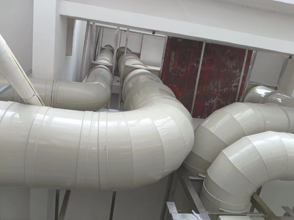
The code’s laboratory provisions require that hazardous exhaust ductwork be under negative pressure while in operation, and the reason is a simple trade of risk: a duct under negative pressure draws air in through any leak, while a duct under positive pressure pushes fumes out. Since the whole point of the system is to keep a hazardous stream away from people, a leak that leaks inward is a much smaller problem than a leak that leaks outward. This is why the fan is placed at the discharge end and why the joints are made tight — the code specifies lap joints with a minimum overlap, and accepts the industrial duct construction standards as an alternative.
The negative-pressure rule also constrains where the duct may run. A duct under negative pressure in an occupied space has to be genuinely tight, because a leak there is a leak into the room, and the code treats ductwork within occupied space more strictly than ductwork in a shaft. The support and hanger system that holds that duct, and the loads it has to carry, are covered in our PP duct installation guide.
Fan Downstream of the Scrubber
The reference arrangement for a chemical fume exhaust duct puts the scrubber upstream of the fan, so the fan handles gas that has already been cleaned. That protects the fan from the corrosive stream: a fan in the raw fume path has to be made of the same exotic material as the duct and is far harder to protect than a straight run of pipe. It also keeps the fan out of the condensate path, since most of the liquid has been removed or drained before the gas reaches it.
The trade-off is pressure: a fan after the scrubber sees a lower pressure than one before it, and the scrubber itself is usually the largest single pressure loss in the system. On a chemical fume exhaust duct the scrubber can account for the majority of the total static pressure, which is why the fan has to be sized on the system curve rather than on a nameplate rating. The full static-pressure budget, term by term, is worked through in our PP duct design and sizing guide.
Routing the Material by Chemistry
Material selection on a chemical fume exhaust duct is a routing exercise, not an argument. Each chemistry class points to a different duct material for reasons that are settled, and the job is to match the stream to the material rather than to defend a favourite. The general case for polypropylene — its grade structure and chemical envelope — is covered in our polypropylene duct guide, and the material-versus-material comparisons in our PP versus PVC, PP versus galvanized and PP versus FRP guides.
The Routing Table
| Chemistry class | Duct routes to | Why |
|---|---|---|
| Mineral acid mist (HCl, H₂SO₄, HNO₃, mixed acid) | PP, PVC or PVDF | Thermoplastics are inert to the acid and can be welded gas-tight; metals corrode at the wet surfaces. |
| Hydrofluoric acid | PP (not FRP) | HF attacks the silica in glass fibre, so an FRP duct loses its structural reinforcement; PP has no silica to attack. |
| Solvent vapor | PP or stainless steel | Solvents attack many coatings and can stress-crack some plastics; material and gasket have to be matched to the solvent. |
| Perchloric acid | PVC or PP, dedicated run, wash-down | Never manifolded; needs a rinse system and a straight, short path to prevent explosive perchlorate residue. |
| Caustic and base fume | PP or PVC | Both resist alkali; PP tolerates the higher temperature of a hot caustic stream. |
| Mixed or unknown stream | Determined by the primary corrosive element | The code requires an analysis of the chemicals to be exhausted, with the material chosen for the primary corrosive element. |
Two entries in that table are the ones buyers get wrong most often. Hydrofluoric acid is widely and wrongly assumed to be an FRP application, when the fibre chemistry makes PP the correct default. And a mixed or unknown stream is not an invitation to pick the most expensive material — it is a prompt to do the analysis the code requires, because the primary corrosive element, not the worst-case guess, is what the wall has to resist.
System Layout: Hood, Duct, Scrubber, Fan, Stack
The same layout carries a set of laboratory-specific requirements that a general hazardous-exhaust duct does not have to meet, because the duct runs inside an occupied building and is governed by a laboratory standard as well as by the mechanical code. Those requirements — no fire or smoke dampers, flow control dampers that fail open, exhaust that keeps running during a fire, and a manifold confined to one laboratory unit — are set out in our guide to laboratory exhaust duct.
Pulled together, the decisions above resolve into a reference arrangement for a chemical fume exhaust duct. The order of the elements is not arbitrary; each one is placed to protect the next and to keep the pressure direction correct.
A Reference Arrangement
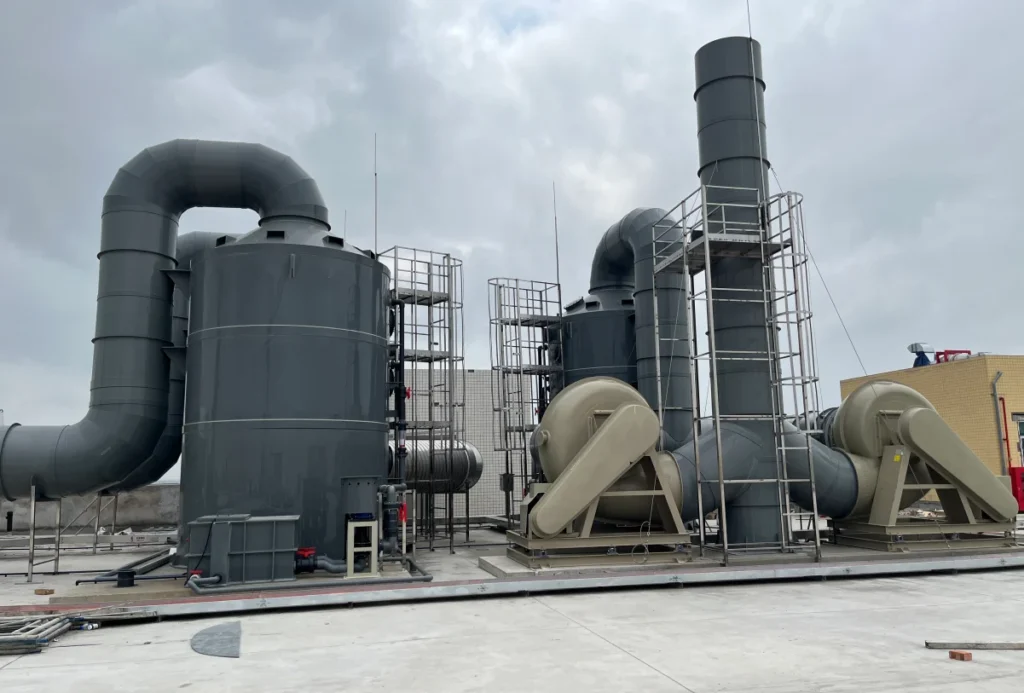
The stream is captured at the hood, drawn into the duct under negative pressure, carried to the scrubber or other air-pollution-control device, cleaned, and then moved by a fan on the clean side to the stack. Along the way the duct slopes to its drain points, avoids horizontal runs that can pool, takes the shortest practical path to the outside, and does not share a duct or a shaft with an incompatible stream. The fan sits downstream of the scrubber so it handles cleaned gas; the stack discharges the diluted stream at a velocity high enough to disperse it.
Each of those elements is a place where a chemical fume exhaust duct differs from general ductwork: the hood sets the capture velocity, the duct sets the transport velocity and the drain points, the scrubber dominates the pressure budget, the fan’s position sets the pressure direction, and the stack sets the discharge. Getting the order right is most of the design; the material is then chosen to survive the duty the arrangement creates.
Standards and Documents to Specify
A specification that names a material should also carry the definition it relies on, because “polypropylene duct” is a family rather than a single material: the grades differ in stiffness and in temperature rating, and a duct specified without a grade is a duct the fabricator specifies. What the material actually covers is set out in our guide to what a PP duct is.
A chemical fume exhaust duct is specified against a document set, not a single product data sheet. On the duct itself, the material has to be named with its grade and its fire-test result, the wall thickness stated, and the joints described. On the system, the hazardous-exhaust provisions of the mechanical code apply, and the fire standards that sit behind them. The list below is the short set to put in writing.
- The material and grade, with the flame-spread and smoke-developed indices from a test report (not a claim of “flame retardant”).
- The wall thickness and the pressure class, stated as positive, negative or both.
- The joint method — welded, flanged or mechanical — and the leak-tightness it achieves.
- The drain and slope schedule, with low points and trap locations marked.
- The wash-down requirement, if any, with the cycle time and coverage.
- The applicable standards — the hazardous-exhaust code section, and where relevant the fire and laboratory standards behind it.
The welding and fabrication quality behind those documents is covered in our PP duct welding and PP duct fabrication guides, and the site-work that follows in our PP duct installation guide.
Frequently Asked Questions
Q: What is a chemical fume exhaust duct?
A: It is the duct system that captures and conveys chemical fumes — corrosive, toxic or flammable vapors, mists and gases — from a process or a fume hood to a safe discharge. Under the mechanical code it is a hazardous exhaust system, which puts it under rules that ordinary ventilation ductwork does not have to meet.
Q: Can a chemical fume exhaust duct be made of polypropylene?
A: Yes, and PP is often the right choice for acid and mixed-acid duty. Where the stream is nonflammable and corrosive, the code requires the nonmetallic duct to show a flame-spread index of 25 or less and a smoke-developed index of 50 or less, which points to flame-retardant PP or rigid PVC rather than standard PP.
Q: Why can’t perchloric acid share a duct?
A: Heated or concentrated perchloric acid can condense in the duct and dry to perchlorate salts that are shock-sensitive and explosive. The code prohibits perchloric acid hoods and their exhaust from being manifolded, so they run as a dedicated system with a wash-down and a short, straight path outdoors.
Q: What velocity should a chemical fume exhaust duct run at?
A: Vapors and gases have an economic optimum of roughly 1,000–2,000 fpm, higher than a comfort-ventilation duct but below the speeds used for particulate. The floor is set by the need to keep the stream entrained; the ceiling is set by the fact that fan power rises with the cube of velocity.
Q: How do I stop condensate collecting in the duct?
A: Slope the duct toward a defined low point and drain it, and avoid dead-level horizontal runs. A saturated scrubbed gas can produce tens of litres of liquid per hour, so the drain is a design element, not an afterthought, and the material has to survive continuous contact with the concentrated liquid.
Q: Why is the fan placed after the scrubber?
A: So the fan handles cleaned gas rather than the raw corrosive stream. That keeps the fan out of the fume path and out of the condensate path, at the cost of a lower inlet pressure — which is why the fan has to be sized on the system curve rather than on a nameplate rating.
Conclusion
A chemical fume exhaust duct is designed in layers, and the material is the last of them. The first layer is the code, which decides what may share a duct, how perchloric acid must be handled, what may be installed inside the duct, and what a nonmetallic wall has to prove. The second is velocity, set by the contaminant rather than by habit. The third is condensation, which on a chemical duct is the real design driver and turns a passive tube into a system with drains, slopes and a defined low point. The fourth is pressure, which decides that the duct runs under negative pressure and that the fan sits on the clean side. Only then does the material choice resolve — and when it does, it resolves by routing the chemistry to the right wall, not by arguing for a favourite. Get the layers right and the duct behaves like the specification; get them wrong and no material is good enough.
If you are specifying a chemical fume exhaust duct, send us the chemistry, the airflow and the operating temperature and we will route the material and the system around them. Our industrial ductwork range covers round, square and rectangular PP duct with matching fittings, and our industrial polypropylene duct customization and square polypropylene duct customization pages show the level of documentation a hazardous-exhaust duct should carry. To start, contact us with the duty.
Sources
- International Mechanical Code, Section 509 — Hazardous Exhaust Systems — UpCodes (text of IMC §509 as adopted in the 2024 Illinois Mechanical Code: incompatible materials and common shafts, perchloric manifolding prohibition, prohibition of fire and smoke dampers, nonmetallic duct flame-spread index ≤ 25 and smoke-developed index ≤ 50, minimum duct thickness table, support spacing, clearance to combustibles).
- NFPA 91 — Standard for Exhaust Systems for Air Conveying of Vapors, Gases, Mists, and Particulate Solids (2026 edition; fire and explosion requirements for exhaust systems conveying vapors, gases, mists and particulate solids).
- NFPA 45 — Standard on Fire Protection for Laboratories Using Chemicals (2024 edition; perchloric acid hood requirements and laboratory exhaust provisions).
- ACGIH — Industrial Ventilation: A Manual of Recommended Practice for Design (the design reference for hood, duct and velocity selection in industrial exhaust systems).
- OSHA — 29 CFR 1910.1450, Occupational Exposure to Hazardous Chemicals in Laboratories (the laboratory standard: chemical hygiene plan and the duty to keep fume hoods and protective equipment functioning properly).
- OSHA — Technical Manual, Section III: Chapter 3 — Ventilation Investigation (capture velocity and hood design practice for local exhaust ventilation).
- Nordfab — Range of Minimum Duct Design Velocities (minimum transport velocity by contaminant class; vapors and gases with an economic optimum of 1,000–2,000 fpm, welding fume 2,000–2,500 fpm).