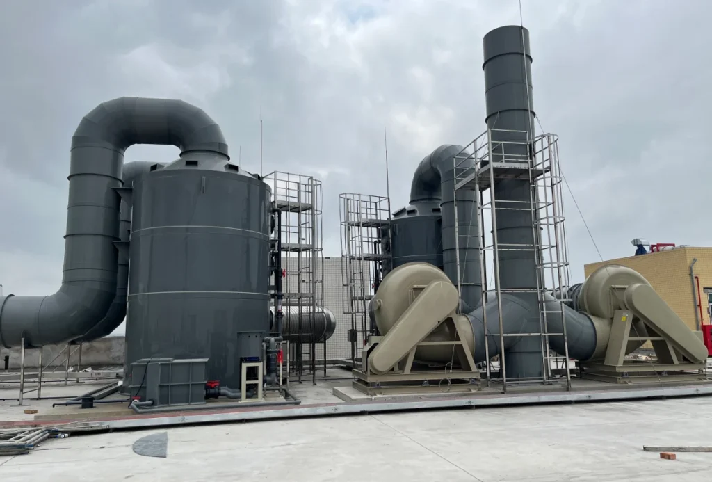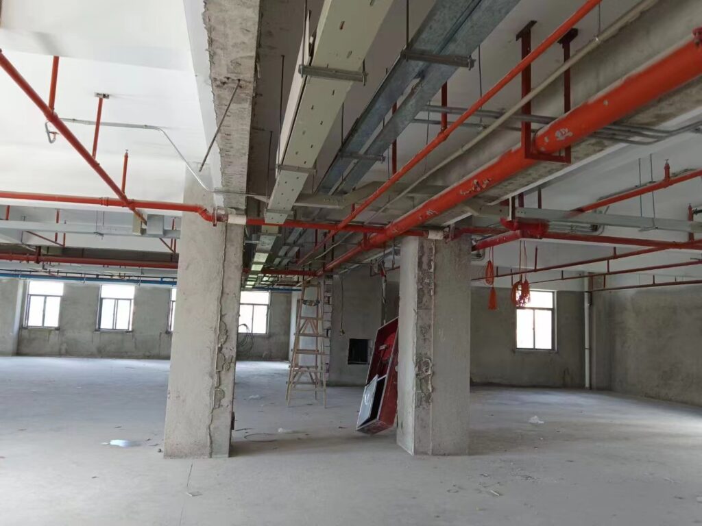
A laboratory exhaust duct is not a plant duct that happens to serve a laboratory. It runs inside an occupied building, it is the containment path that carries a fume hood’s contents to a safe discharge, and it is bound by a laboratory-specific standard set that ordinary ventilation ductwork never sees. Get the material right and the layout wrong, and the duct still fails — because in a lab the duct is judged by where it runs, what it is joined to, and what happens when the airflow drops, not by the material alone. This guide works through the duct layer of a laboratory exhaust system: the provisions NFPA 45 actually puts on the duct, the manifold and diversity arithmetic that decides the layout, the velocity a lab duct is really sized on, the material question beyond the familiar “PVC or 316 stainless” default, and the stack that is simply the last section of the duct.
Key Takeaways
- The duct is the containment path, and it runs through occupied space. A leak in a laboratory exhaust duct does not vent to atmosphere — it vents into the building, which is why the whole run is held under negative pressure and every joint is specified, not inherited.
- NFPA 45 forbids fire and smoke dampers in a lab exhaust duct, and requires flow control dampers to fail open. The same standard requires exhaust to keep running during a hood fire: shutting the fan down pushes combustion products back into the room.
- A manifold is permitted only within one laboratory unit, and some streams never share a duct at all. Perchloric acid hoods, radioisotope hoods and HEPA-filtered cabinets stay dedicated.
- Face velocity is not duct velocity. A hood holding 100 fpm at the sash produces roughly fifteen times that inside a 250 mm duct, and the duct velocity is set by the manifold’s turndown — not by the contaminant.
- The common default fails where it matters most. 316 stainless is non-resistant to hydrochloric acid at any concentration or temperature, and rigid PVC is capped near 60 °C. Polypropylene covers both cases, and is weak where solvents are the stream.
- The stack is part of the duct system, not a fitting on the roof. It has a minimum exit velocity of about 3,000 fpm, a height set against the building’s recirculation zone, and a location chosen to keep its own discharge out of the intakes.
What a Laboratory Exhaust Duct Has to Do
Every exhaust duct moves air from one place to another. A laboratory exhaust duct does something more specific: it carries a stream that is corrosive, often condensable, sometimes acutely toxic, and it does so through a building that people are working in. That single fact — the duct passes through occupied space — changes almost every design decision downstream of the hood.
The Duct Is the Containment Path
A fume hood contains a spill or a reaction at the sash. Everything downstream of the hood — the branch duct, the manifold, the fan, the stack — is the path by which the contained air leaves the building. If that path leaks, the containment the hood provides is undone: the contaminated air is delivered into the laboratory or into the ceiling void rather than to the discharge point. This is why a laboratory exhaust duct is normally run at a pressure below that of the rooms it passes through. A leak in a negative-pressure duct draws room air into the duct. A leak in a positive-pressure duct pushes the stream out into whatever the duct is passing through.
The practical consequence is that the duct material and the duct pressure are not independent choices. The material has to survive the stream, and the run has to be arranged so that any failure of a joint, a seam or a fitting fails inward. The fan selection that makes this possible is covered in our guide to the fume cupboard exhaust fan; this article stays on the duct side of that boundary.
Why a General-Exhaust Rule Does Not Transfer
General ventilation ductwork is sized to move air for comfort, and its failure mode is poor performance. A laboratory exhaust duct is sized to move a contaminant, and its failure modes include corrosion through the wall, condensate pooling at a low point, and a joint that opens under chemical attack. The standards treat the two as different systems for that reason. A laboratory exhaust duct that carries hazardous vapour is a hazardous exhaust system, and it inherits rules that a comfort-ventilation duct never has to meet — rules about what may not be installed in it, what it may not be joined to, and what must keep running when everything else stops.
The Code Layer: What NFPA 45 Requires of the Duct
Two standards overlap on a laboratory exhaust duct. The mechanical code governs hazardous exhaust generally; NFPA 45, Fire Protection for Laboratories Using Chemicals, governs the laboratory specifically. The general hazardous-exhaust provisions are worked through in our guide to the chemical fume exhaust duct. What follows is the layer that is particular to a laboratory, and it is where most of the duct’s design constraints actually come from. NFPA 45 is published by the National Fire Protection Association.
Dampers Are Prohibited — and Flow Dampers Must Fail Open
A fire damper or a smoke damper is a standard element of ordinary ductwork, and it is not permitted in a laboratory exhaust duct. A damper that closes on a fire signal would seal the duct at exactly the moment the hood needs to keep venting, and it would convert the duct into a closed vessel holding combustion products. Institutional design standards state the prohibition plainly: fire and smoke dampers are not allowed in laboratory exhaust ductwork per NFPA 45.
There is a second, subtler provision. A flow control damper — a balancing or volume damper added for airflow reasons, not for fire — is permitted, but it must be arranged to fail open. If its actuator loses power or its linkage fails, the damper has to move to the open position rather than closing. The reasoning is the same as the fire-damper prohibition: on a laboratory exhaust duct, a damper that closes by accident is more dangerous than one that stays open.
Exhaust Is Never Shut Off in a Fire
The instinct during a hood fire is to stop the airflow. NFPA 45 requires the opposite. The exhaust system is required to keep running, and the standard uses mandatory language throughout that provision. The reasons are practical: stopping flow would send the combustion products — carbon monoxide, soot, aromatic hydrocarbons — back into the laboratory instead of out of it; a running exhaust removes heat as well as fume, and a cutoff would raise the temperature inside the hood and hasten the failure of its structure; and the people leaving the room need the makeup air that the exhaust is pulling in. A laboratory exhaust duct is therefore designed on the assumption that it will be asked to run during the worst event, not shut down for it.
The Duct Must Be Compatible With What It Carries
NFPA 45 requires the ductwork to be compatible with the materials being conveyed, and it requires the ductwork to be noncombustible except where a listed nonmetallic material is permitted. The compatibility clause is deliberately open-ended, and it is also the clause that quietly fails over time: a duct installed for a dilute stream becomes a concentrated stream when a variable-air-volume system is retrofitted and the airflow is reduced, because the same mass of contaminant is now carried in less air. The duct does not know that the chemistry changed; the design has to.
The Nonmetallic Exception: Flame Spread 25, Smoke 50
Where a nonmetallic duct is used, the standard’s exception sets two numbers: a flame-spread index of 25 or less and a smoke-developed index of 50 or less, tested to ASTM E84 or UL 723. Both numbers are required together. A material can be a legitimate Class A building material with a flame-spread index of 24 and a smoke-developed index well above 50 and still fail this clause, because the pair is what is specified. This is the provision that decides which grades of polypropylene, PVC and FRP are even admissible in a laboratory exhaust duct, and it is treated in full in our guide to the flame retardant PP duct.
Manifolded or Dedicated: The Layout Decision
The first layout question on a laboratory exhaust duct is whether it serves one hood or many. Both arrangements are used, and the choice is governed by a single provision of NFPA 45 plus a short list of streams that are excluded from it.
Section 7.5.10.3 — One Laboratory Unit
Where several items of laboratory exhaust-producing equipment are connected to a common duct, the standard requires that all of them be located within the same laboratory unit. A laboratory unit is not a room; it is the group of laboratories under the administrative control of one Laboratory Director, appointed in writing, who is responsible for the chemical inventory and for judging whether the streams are compatible. That definition does the work: it means a manifold may combine hoods that answer to the same person and the same inventory, and it does not extend to connecting a hood to exhaust from a waste room, a cold store or a growth room, which belong to different hazard profiles and often to different directors. Each manifolded system is also required to have a dedicated exhaust fan, so that one fan failure does not take down a shared system without redundancy.
The Streams That Never Share a Duct
Even inside one laboratory unit, three classes of exhaust are kept dedicated rather than manifolded. Perchloric acid hoods run alone, because heated perchloric acid can condense in the duct and dry to shock-sensitive perchlorate salts, and because the duct needs a wash-down that no other stream should share. Radioisotope hoods run alone, because the contamination is not destroyed by dilution and the duct has to remain surveyable. Biological safety cabinets that exhaust through HEPA filtration run alone, because a manifold would put the filter upstream of streams that would not tolerate it and would make the cabinet’s certification meaningless. A manifold is a tool for combining compatible streams; it is not a way to avoid running a second duct where a second duct is the requirement.
What a Manifold Actually Buys
Manifolding is not a cost shortcut. The consensus position of the committee behind ANSI/AIHA Z9.5, the laboratory ventilation standard, is that manifolding fume hood exhausts is safer in almost every case than one fan per hood. The reasons are operational: a manifolded system with two or more fans has backup capacity that a single-fan-per-hood arrangement does not, its fans can be run at part load in rotation, and a manifolded stack discharges a larger, more dilute, higher-momentum plume than a series of small individual stacks, which disperses it more effectively. The general laboratory ventilation practice this draws on is published by ACGIH. The material and size questions that a manifold raises are the same ones that govern any PP duct run, set out in our guide to polypropylene duct.
The Diversity Factor, Worked
A manifold is almost never sized to carry the sum of every hood it serves at full sash. It is sized on a diversity factor — an allowance that not every hood will be at full flow at the same moment.
Sizing the Manifold Below the Sum of the Hoods
Take eight fume hoods, each drawing about 1,300 m³/h at full sash. The arithmetic sum is 10,400 m³/h. If the design assumes a diversity factor of 0.7 — that at any instant roughly seven of the eight are effectively at full flow — the manifold and its fan are sized for 7,280 m³/h instead of 10,400. That reduction is what makes a manifold smaller and cheaper than the ducting it replaces, and it is also what sets the duct’s velocity range, because the manifold has to hold a minimum transport velocity at the low end of its operating range and not exceed a practical limit at the high end.
The Assumption You Have to Put in Writing
The diversity factor is a design assumption, not a code value, and it is the number most likely to be wrong. It assumes the laboratory will keep behaving as it does at design time: the same number of hoods, the same operating hours, the same habits. If a new programme adds hoods, or if the same hoods are used simultaneously for a longer shift, the real flow rises toward the arithmetic sum and the manifold is undersized. Institutional guidance is explicit that diversity should be applied with caution and with the laboratory’s likely growth in mind. A defensible design states the diversity factor, the basis for it, and the headroom left for future hoods, so that the number can be revisited rather than discovered.
Duct Velocity in a Laboratory
Velocity is where laboratory exhaust ducts are most often mis-specified, because two different velocities are in play and they are frequently treated as one.
Face Velocity Is Not Duct Velocity
Face velocity is measured at the plane of the hood opening, and it is the number that describes containment. Institutional design standards put a standard chemical fume hood at an average face velocity of about 100 fpm, with single-point readings in the 80–120 fpm band acceptable, and reduced-face-velocity hoods at about 70 fpm. That is a velocity at the sash, not in the duct.
The duct velocity is set by the same airflow passing through a much smaller area. Take a hood with a 1.2 m × 0.6 m opening — 0.72 m² — holding 100 fpm, which is 0.508 m/s. The volume flow is 0.72 × 0.508 = 0.366 m³/s, or about 1,317 m³/h. Pass that through a 250 mm duct, whose area is 0.0491 m², and the velocity is 0.366 ÷ 0.0491 = 7.45 m/s, which is about 1,467 fpm. The duct is running at roughly fifteen times the face velocity. Anyone who sizes a laboratory exhaust duct at the face-velocity number will produce a duct far too large, and anyone who reads a duct velocity as a containment figure will misjudge the hood.
Why the Manifold Sets the Velocity, Not the Contaminant
In a single-hood duct, the transport velocity is set by the contaminant — the speed needed to keep the stream entrained rather than settling. In a manifolded laboratory exhaust duct, the governing velocity is usually set by something else: the need to hold a minimum velocity at the lowest flow the system will see, which is the moment when most hood sashes are closed. That minimum is what fixes the manifold’s size. The velocity the duct sees at design flow is a consequence of that choice, not the starting point.
The 500 fpm Floor and the 5:1 Turndown
Laboratory exhaust systems are commonly designed within a band from about 500 fpm at the minimum to about 2,500 fpm at the design maximum. That band is a turndown ratio of 5:1 — the system can fall to 20% of its design airflow and still hold the 500 fpm floor, which is what keeps a condensable vapour from lingering long enough to deposit and what keeps a particulate from settling in a horizontal run. The upper limit is set by the cost of going faster: because pressure drop rises with the square of velocity and fan power with its cube, a 40% increase in duct velocity roughly doubles the pressure drop in that section and increases the fan energy by nearly three times. Balancing the two ends of that range is the whole of laboratory duct sizing, and the general method is worked through in our guide to PP duct design and sizing. The fittings that consume much of the pressure available are covered in our guide to PP duct fittings.
Choosing the Material Beyond “PVC or 316 Stainless”
The most repeated advice on laboratory ductwork is that there are two materials: Type 1 PVC and Type 316 stainless steel. It is a useful starting point and a poor finishing point, because the two materials fail on the two most common laboratory services.
The Default Two, and Where Each One Fails
Rigid PVC is a genuine workhorse for corrosive aqueous streams at low temperature, and it is inexpensive and easy to weld. Its limit is temperature: rigid PVC duct is capped at about 60 °C (140 °F) for continuous service, and above that it loses stiffness and sags between supports before it fails outright. That ceiling rules it out of most hot exhaust, which is a large fraction of laboratory service. Type 316 stainless steel is the other default, and it is a good material for solvents, which do not attack it. Its limit is different: stainless steel is not the answer for acid, and in particular not for hydrochloric acid.
Hydrochloric Acid: Why 316 Is Not the Answer
Hydrochloric acid is a reducing acid, and it lacks the oxidising character that stainless steel needs to maintain its passive surface layer. The assessment published by the British Stainless Steel Association is unambiguous: the common grades 304 and 316 should be considered non-resistant to hydrochloric acid at any concentration and temperature, and higher-alloyed stainless grades have only limited resistance, up to about 3% at ambient, and can still suffer crevice and pitting attack even at those low concentrations. Any additional chloride in the stream makes the attack more severe. This is the trap in the phrase “chloride resistance”. Type 316L is preferred over 304 in near-neutral chloride service such as salt-laden air, and that advantage does not carry over to hydrochloric acid, which is one of the most common reagents a laboratory hood will ever exhaust. A duct specified in 316 stainless for an HCl service is specified against the wrong material, however corrosion-resistant the grade sounds.
Where Polypropylene Fits
Polypropylene covers the ground that the two defaults leave open. It is resistant to hydrochloric, sulphuric and nitric acid and to wet chemistry across a broad range, and it is a thermoplastic that can be welded into a continuous, leak-tight run without the cut-edge and weld-zone problems that a coated metal duct carries. Its continuous service ceiling for the duct grades is about 90–100 °C, well above the 60 °C that rules PVC out of hot service. Its weakness is the mirror image of stainless steel’s: aromatic and chlorinated solvents — benzene, toluene, MEK, chloroform — can swell or degrade it, so a solvent-heavy hood is the case where stainless steel, not PP, is the right answer. The acid-versus-solvent split is the single most useful screen on a laboratory duct, and the acid side of it is treated in our comparison of PP duct versus PVC duct and PP duct versus galvanized duct. Where the stream is hydrofluoric acid, the material ranking inverts, and that case is worked through in our guide to PP duct versus FRP duct.
The Temperature Ceiling, and the 140 °F Confusion
Laboratory duct material data sheets quote polypropylene limits across a wide band, and one common figure — about 140 °F, which is 60 °C — is the PVC number, not a polypropylene limit. The duct grades of polypropylene homopolymer are rated for continuous service at roughly 90–100 °C, and the melting point of those grades sits near 160–170 °C; the rating is a creep limit, not a softening point, which is why it is quoted as a band rather than a single figure and why it depends on the grade and the load. The full basis for the figure is in our guide to what a PP duct is. Reading a 140 °F figure as a polypropylene ceiling is the single most common material error on a laboratory exhaust duct, and it usually leads to a metal duct being chosen for a service that polypropylene would have handled.
Joints, Supports and Condensate in a Lab Run
Once the material is right, three construction details decide whether the duct performs: how it is joined, how it is supported, and how the liquid that forms inside it is removed.
Joints That Survive the Service
A laboratory exhaust duct is joined the way the material allows. A thermoplastic run is welded — hot-gas or extrusion welding on site, or heat-fused socket joints — into a continuous wall with no mechanical fasteners through it. A metal run in an aggressive service is often orbitally welded to produce a smooth, full-penetration seam with no gaps for the stream to collect in. What matters is that the joint method matches the chemistry: a taped-and-mastic joint is legitimate on dry, non-corrosive exhaust and is not legitimate on acid service, where the sealant degrades and the joint becomes both a leak path and a corrosion point. The welding procedures and joint strength for a thermoplastic duct are set out in our guide to PP duct welding, and the fabrication behind them in our guide to PP duct fabrication.
Supports at Plastic Spacing
A thermoplastic duct is supported at closer intervals than a metal duct of the same size, because its stiffness is lower and it creeps under sustained load, and the spacing tightens further as the duct gets larger. The spacing is a property of the material and the diameter, not a matter of site judgement, and getting it wrong shows up as sag between hangers rather than as an immediate failure. The per-diameter figures and the hanger loads that go with them are in our guide to PP duct installation, and the size ladder they refer to is in our guide to PP duct size and thickness.
Slope Back to the Hood
A laboratory exhaust duct carries moisture. A wet scrubber or a wash-down adds it, a humid process stream contains it, and a saturated stream that cools on its way to the stack will release it as liquid. The laboratory convention for handling it is different from a plant duct: the duct is sloped back toward the hood, so that any condensate formed in the run drains to the hood rather than to the main lateral or to a low point in the middle of the run. The hood is built with a drain trough and a drain lip for exactly this reason, piped to a local floor drain. The rule is worth stating plainly because it inverts the instinct from process ductwork: on a laboratory exhaust duct the liquid goes back to the source, not forward to the stack, and a run that has been laid dead level has nowhere for the liquid to go at all.
The Stack Is the Last Section of the Duct
The stack is usually drawn as a roof fitting. It is better understood as the final section of the exhaust duct, because the same design logic applies: it has to carry the stream, and it has to deliver it somewhere the stream will not come back.
Exit Velocity: The 3,000 fpm Floor
A laboratory exhaust stack is designed with a minimum discharge exit velocity, so that the plume is thrown clear of the building rather than allowed to curl back down onto the roof. Institutional design standards put that minimum at about 3,000 fpm — 15.2 m/s — unless a dispersion study demonstrates that a lower tip velocity achieves the required dilution. The figure is not arbitrary: it is the velocity that, combined with stack height, keeps the discharge above the recirculation zone that forms in the lee of the building. The design guidelines for laboratory exhaust fans and stacks published by AIVC use the same 3,000 fpm figure, together with a 15 mph (6.7 m/s) design wind speed.
Stack Height and the Recirculation Zone
Stack height is set against the building’s own aerodynamics, and the governing quantity is the length of the recirculation zone on the leeward side — the region where the airflow separates from the roof and can carry a plume back down. A geometric method in common use estimates that zone as R = Bsmall0.67 × Blarge0.33. For a building 60 ft high and 100 ft wide, that gives R = 600.67 × 1000.33 = 71 ft (21.6 m). A stack at the centre of a 200 ft-long roof must therefore throw 100 ft to the roof edge plus 71 ft to clear the zone, a throw of 171 ft (52 m). Because the plume is pushed downward at roughly a five-to-one slope from the top of its throw, the effective stack height above the fan is 171 ÷ 5 = 34.2 ft (10.4 m), and after the minimum fan-and-stack height of 10 ft (3.05 m) recommended by Z9.5, the throw still required above the fan is 24.2 ft (7.38 m). The ASHRAE Handbook relationship used to turn that into a stack geometry is: effective stack height = 3 × stack diameter × stack exit velocity ÷ wind velocity. At 3,000 fpm exit velocity and a 15 mph wind, a stack sized for 30,000 cfm satisfies the 24.2 ft requirement, while a stack carrying only 10,000 cfm at the same exit velocity delivers only about 14 ft and falls short. The lesson is that a stack cannot be sized on velocity alone; the volume it carries is part of the height calculation. Institutional standards also set a simple floor: extend stacks a minimum of 10 ft above the highest local roof.
Re-Entrainment, and Why Stacks Are Clustered
Re-entrainment is the failure the stack exists to prevent: discharge that leaves the stack and is drawn back into a building intake, an open window or an air-handling unit. It is managed by three things at once — height, exit velocity, and location. Stacks are placed as far as the layout allows from intakes, and where a choice exists they are clustered or grouped rather than spread out, because a group of stacks produces a single larger and more buoyant plume that disperses better than the same volume split into scattered small plumes. The stack geometry and the duct that feeds it are therefore designed together, and the same PP duct that runs inside the building continues up the stack. The materials and sections used for that final run follow the same rules as the rest of the system, set out in our guide to polypropylene duct.
Where the Fan Goes, and Why the Duct Cares
The fan’s position is a duct decision as much as a fan decision, because it determines the pressure the duct sees along its whole length.
Negative Pressure for the Whole Run
The fan is placed so that the entire in-building duct run is under negative pressure relative to the rooms it passes through. That is the arrangement that makes a leak fail inward. In practice this means the fan sits at the end of the run, at the roof, drawing air through the building rather than pushing it through. Where a fan has to be indoors — in a mechanical penthouse or plant room — the enclosure around it is made airtight and the discharge duct from the fan is seal-welded, so that any leakage is contained rather than released into the space where maintenance staff work.
Why the Fan Belongs on the Roof
Field measurement has shown why the roof is the preferred location. Studies of laboratory exhaust leakage have found that enclosing exhaust fans in penthouses exposes maintenance workers to contaminant concentrations that are not acceptable, and that the largest single leakage source is the flexible connector at the fan discharge — it leaked almost twice as much as the next-largest source, with the duct, fittings, the fan housing and the shaft seal accounting for the rest. Placing the fans on the roof, outside the building envelope, removes the exposure pathway at its source. The leakage itself is detected with the same tracer-gas methods used to test hood containment, which is the subject of the next section. Fan selection for that duty is covered in our guide to the fume cupboard exhaust fan.
Testing, Balancing and Staying Compliant
A laboratory exhaust duct is not commissioned once and forgotten. The system drifts, and the drift is the hazard.
Tracer-Gas Containment Testing
The performance of a fume hood is measured with a tracer-gas method — a known tracer is released inside the hood and its concentration is measured at the operator’s breathing zone and around the sash, to establish that the containment holds under the real conditions of the room. The test is defined by ASHRAE Standard 110, Method of Testing Performance of Laboratory Fume Hoods, and the same tracer-gas technique is used to locate leakage in the exhaust system itself, which is how the flex-connector finding above was produced. Containment testing is the acceptance test for the hood-and-duct system as a whole, and it belongs in the commissioning scope rather than being treated as a vendor demonstration.
Airflow Alarms and Annual Verification
Because a laboratory exhaust duct’s performance depends on airflow that can drift, the system carries monitoring. A hood is normally fitted with a flow monitor and an alarm that reports when the airflow falls outside its set band, and the duct’s own airflow is verified at commissioning and after any change that affects the balance — a hood replacement, a fan-speed change, a filter change, or a reconfiguration by another trade. The failure modes are ordinary: a loaded filter raises the system resistance, a damper drifts out of adjustment, debris from a renovation restricts the duct, and any one of them can pull the velocity below the transport floor without any obvious symptom. A laboratory exhaust system is also subject to periodic re-verification, and the annual interval is the one to plan around.
When the Chemicals Change
The most common way a compliant laboratory exhaust duct becomes a non-compliant one is that the chemistry changes and nobody re-checks the duct. Two mechanisms do the damage. The first is a change of substance: a new programme introduces a reagent the duct material was never selected for. The second is subtler and is a by-product of energy saving. When a variable-air-volume system is retrofitted and the exhaust flow is reduced, the same mass of contaminant is carried in less air, so the concentration in the duct rises. A duct that was specified for a dilute stream is now carrying a concentrated one, at the same velocity floor and through the same material. Both mechanisms argue for the same discipline: record the material each duct run is made of, and re-check compatibility whenever the inventory changes. The chemical-resistance and code questions that a re-check raises are covered in our guide to the chemical fume exhaust duct.
Frequently Asked Questions
What is a laboratory exhaust duct?
It is the duct system that carries fume-hood and local-exhaust air from a laboratory to a safe discharge. Under the mechanical code it is a hazardous exhaust system, and under NFPA 45 it is subject to laboratory-specific rules: no fire or smoke dampers, flow control dampers that fail open, exhaust that keeps running during a fire, and a duct material compatible with what it carries. It runs through occupied space, so it is normally held under negative pressure and joined leak-tight.
Can a laboratory exhaust duct be made of polypropylene?
Yes, and polypropylene is often the right material for acid and mixed-acid duty. Where the stream is nonflammable and corrosive, the code requires the nonmetallic duct to show a flame-spread index of 25 or less and a smoke-developed index of 50 or less, which points to flame-retardant PP or rigid PVC rather than standard PP. PP’s advantage over PVC is temperature — about 90–100 °C continuous against PVC’s 60 °C — and over stainless steel it is the acid service that matters, since 316 stainless is non-resistant to hydrochloric acid. PP’s limit is solvent service, where stainless steel is the better choice.
Can two fume hoods share one exhaust duct?
Yes, provided both hoods are in the same laboratory unit under one Laboratory Director and their streams are compatible, and provided the manifolded system has a dedicated exhaust fan. Perchloric acid hoods, radioisotope hoods and HEPA-filtered biological safety cabinets are kept on dedicated ducts regardless. The manifold is then sized on a diversity factor rather than on the sum of all hoods at full flow.
What velocity should a laboratory exhaust duct run at?
Laboratory exhaust ducts are commonly designed within about 500 fpm at minimum flow to about 2,500 fpm at design maximum — a 5:1 turndown, so the system can fall to 20% of design airflow and still hold the transport floor. The duct velocity is not the hood’s face velocity: a hood holding 100 fpm at the sash drives roughly fifteen times that velocity in a 250 mm duct. The minimum is set by the need to keep the stream entrained; the maximum by the fact that fan power rises with the cube of velocity.
Why can’t a fire damper go in a lab exhaust duct?
Because closing the duct during a fire would seal the exhaust at the moment it is most needed, sending combustion products back into the laboratory instead of out of it, and turning the duct into a closed vessel holding hot gases. NFPA 45 prohibits fire and smoke dampers in laboratory exhaust ductwork, and requires flow control dampers fitted for airflow reasons to fail open rather than closed.
How high should a laboratory exhaust stack be?
High enough that its plume clears the building’s recirculation zone and does not re-enter an intake. Institutional standards set a floor of at least 10 ft above the highest local roof and a minimum discharge exit velocity of about 3,000 fpm, and the geometric method sizes the height from the recirculation zone, which scales with the building’s dimensions. The stack’s volume matters too: at the same exit velocity, a small stack produces a much shorter effective throw than a large one, so height cannot be judged from velocity alone.
Conclusion
A laboratory exhaust duct is designed against three things at once: the chemistry it carries, the code that governs a laboratory, and the building it runs through. The chemistry decides the material, and the honest answer is rarely the familiar pair of PVC and 316 stainless — PVC is capped near 60 °C and stainless steel is non-resistant to hydrochloric acid, which leaves polypropylene covering the acid side and stainless steel the solvent side. The code decides the layout: a manifold only within one laboratory unit, no fire dampers, flow control dampers that fail open, and an exhaust that keeps running in a fire. The building decides the velocity and the stack, because the duct has to hold a transport floor at its lowest flow and deliver its plume above the recirculation zone. Get all three right and the duct does its job quietly for the life of the laboratory; get the material right and the layout wrong and it will still fail.
If you are specifying a laboratory exhaust duct and want the material and the sections worked against your actual chemical inventory, the duct range is set out under industrial ductwork, including the custom round PP duct and custom square PP duct sections. Send us the stream, the continuous temperature and the run, and we will come back with a material and a size. Contact us to start.
Sources
- National Fire Protection Association — NFPA 45, Standard on Fire Protection for Laboratories Using Chemicals (laboratory exhaust duct provisions, dampers, manifolding within a laboratory unit, compatibility with conveyed materials).
- ACGIH — Industrial Ventilation: A Manual of Recommended Practice (the practice behind ANSI/AIHA Z9.5 laboratory ventilation; duct and hood design basis).
- AIVC — Design Guidelines for Laboratory Exhaust Fans and Stacks (manifolding consensus, 3,000 fpm minimum exit velocity, geometric stack-height method, fan leakage findings).
- University of Michigan, Architecture, Engineering and Construction — Laboratory Ventilation Design Guideline (100 fpm face velocity, damper prohibition, roof-mounted fans, 3,000 fpm stack exit velocity, condensate drain-back to hood).
- British Stainless Steel Association — Selection of stainless steels for handling hydrochloric acid (HCl) (304 and 316 considered non-resistant to HCl at any concentration and temperature).
- Occupational Safety and Health Administration — 29 CFR 1910.1450, Occupational Exposure to Hazardous Chemicals in Laboratories (the Laboratory Standard and the Chemical Hygiene Plan).