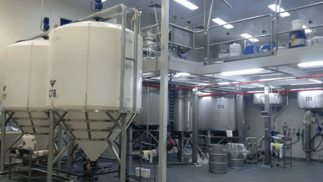
A cone bottom tank is a vertical cylinder with a cone for a lower head. Written that way it sounds like a variant of a storage tank, and in some catalogues it is one. The flat-bottom vessel it is measured against carries its own trade-offs, from the base detail to the heel left under the outlet, and that side of the comparison is in flat bottom versus cone bottom. In service the difference is structural. The flat floor is replaced by a surface that is inclined everywhere, so nothing inside the vessel can come to rest on it and every particle has somewhere to go. That is the entire value of the shape, and the rest of the design exists to keep that promise: the angle has to be steep enough for the contents, the outlet has to sit where the cone ends, the stand has to hold the result at a height that still works under the ceiling.
Most of the decisions on a cone bottom tank are made before anyone discusses material. They are made when the angle is chosen, when the outlet is placed on the drawing, and when the stand is sized. This page takes those three in that order, then the seam that joins the cone to the shell, then the duties where the shape pays for itself. Resin chemistry and chemical-resistance ratings are treated in our polypropylene tank guide, and the vessel that combines a cone with an agitator gets its own section here only because the shape changes the answer.
Key Takeaways
- A cone bottom tank is specified by three numbers: the cone angle, the outlet size and position, and the height the stand adds. Capacity is the fourth number, and the first three decide it.
- “60° cone” describes two different vessels depending on which datum the shop used. A 60° slope off the horizontal is a 60° included angle; 60° off the vertical axis is a 120° included angle, which is a shallow cone.
- On the same 1,500 mm tank, a 15° cone is 2.61 m deep and a 60° cone is 0.40 m. The shallow cone adds 1,648 L of capacity; the steep one adds 255 L.
- A side outlet whose invert sits 150 mm above the apex leaves 1.2 L behind at 30°, 3.5 L at 45° and 10.6 L at 60°. Steeper does not mean drier unless the outlet is at the true apex.
- Pumping 500 L/min out of a cone bottom tank requires 500 L/min of air back in. A vent sized like an afterthought is the most common way to collapse a cone.
- We weld cone bottoms in polypropylene sheet from 5 mm to 30 mm, test the vessel at 1.5 times design head, and warrant the body and welds for 12 months.
What a Cone Bottom Tank Is — and the One Job It Does
The engineering definition is short. A cone bottom tank is a vertical cylindrical shell closed at the bottom by a right cone and at the top by a flat, dished or open head, with the discharge at the low point. The circle is not incidental: a right cone needs a circular plan, so a rectangular vessel gets a sloping or pyramidal floor instead, and with it a different set of wall loads — the stiffener-led case set out in rectangular plastic tank design. Everything that makes the shape useful follows from the geometry of that lower head: the cross-section shrinks toward the outlet, the wetted surface is never level, and gravity alone carries the contents toward one opening.
The practical definition is a little longer, because a cone bottom tank is also a vessel whose overall height is a design variable. A storage tank of a given volume has a fixed height once its diameter is fixed. A cone bottom tank does not. Its height depends on the angle, and the angle depends on what is inside, and the two of them together decide whether the vessel fits in the room you have.
Two Names for One Shape, and Why the Difference Matters on a Spec Sheet
Buyers call the same vessel a cone bottom tank, a conical bottom tank, a conical tank, a cone tank or a hopper bottom tank, and suppliers use the words interchangeably. The trades do not. In brewing, a conical tank is usually a fermenter with the cone on top, which is the opposite arrangement and a different design problem. In dry bulk handling, a hopper bottom means a vessel that discharges powder or granules rather than liquid, and the angle is chosen from the material’s flow behaviour rather than from its viscosity.
That matters when you read a specification, because “cone bottom” on its own does not describe the geometry. Four details do: the angle and the datum it is measured from, the cone height, the outlet size and position, and whether the stated capacity includes the cone. Two quotations at the same nominal volume can differ by more than a metre of height and by several hundred litres of cone volume, and both can be honestly described as a cone bottom tank.
Discharge Is the Job; Suspension Is Not
A flat-bottomed tank needs something to move its contents to the outlet: a pump with a foot valve, a sweep arm, a sloped floor cast into the base, or a person with a hose. This vessel needs a valve. The cone turns a horizontal floor into a converging funnel, so the last of the contents arrives at the outlet without help, and a vessel that drains by itself is a vessel that can be cleaned and turned over without being entered.
The same geometry is a poor choice for a different task. If the duty is to keep solids uniformly suspended, a cone works against you: it collects the solids into the smallest volume in the vessel, at the lowest point, which is exactly where they settle first and hardest. Suspension is a mixing problem, solved with the right impeller in a vessel whose floor does not funnel material away from it. A vessel with a mixer can be made to work, and the section on mixing below explains what changes, but the shape is not helping.
The Four Decisions That Follow From the Shape
Once the cone is on the drawing, four decisions are forced and none of them can be deferred to the supplier. The angle sets what will leave under gravity and how much height the vessel costs. The outlet sets how fast it leaves, how completely, and what valve will fit. The stand sets where the outlet lands and what carries the load. The seam sets how the cone is joined to the shell and how the joint is proved.
The order matters, because each decision constrains the next. An angle steep enough for a settled sludge produces a deep cone, which produces a tall vessel, which sets the stand height and the pump position. A shallow angle keeps the vessel short but leaves a heel that no valve will pull out. The outlet cannot be sized before the solids are known, and the stand cannot be drawn before the outlet position is known. Working in that order is what turns a shape into a specification.
The commonest mistake is to work in the reverse order, and it is usually invisible until the vessel arrives. A stand is chosen from a catalogue, or reused from a previous installation, and the vessel is then drawn to fit it. The angle gets set by whatever height is left, the outlet lands where the stand allows rather than where the cone ends, and the result is a tank that discharges most of its contents. Nothing on the drawing is wrong in isolation. The sequence was wrong, and the sequence is what the four decisions are for.
Cone Angle: The Number That Decides Everything
Cone bottom tank design reduces to one number more often than suppliers admit. The angle fixes the height, the height fixes the capacity, the capacity fixes the batch size, and the whole thing fixes whether the vessel can be installed where it is needed. It is also the number most often given as a word rather than a dimension, which is how two shops end up quoting the same “60° cone” for two different vessels.
Horizontal or Vertical? Two Ways to Measure the Same Cone
Every conical tank has one unambiguous dimension: the included angle at the apex, measured between opposite walls. Everything else is a convention. A shop that measures the slope of the wall from the horizontal and a shop that measures the half-angle from the vertical axis both call their result “the cone angle”, and the two numbers add up to 90° for the same vessel.
The consequences are large. A cone described as 60° off the horizontal has an included angle of 60° and a wall that rises steeply, one metre of rise for every 0.58 m of run. A cone described as 60° off the vertical axis has an included angle of 120° and a wall that rises one metre for every 1.73 m of run, which is a shallow dish with a hole in it. Both are honestly called a 60° cone by the people who drew them.
The fix is a sentence in the enquiry rather than an argument later: state the included angle, and state the cone height. Two numbers settle it, because the height follows from the angle and the diameter, and any inconsistency between the three shows up immediately. A drawing that gives the diameter, the cone height and the included angle is self-checking. One that gives only “60° cone” is not.
The Geometry You Can Calculate Before You Order
A truncated cone has two useful formulae, and both can be worked out on the back of the drawing. The height of the cone is h = (R − r) / tan θ, where R is the radius at the top of the cone, r is the radius at the outlet, and θ is the wall angle measured from the horizontal. The volume is V = πh / 3 × (R² + Rr + r²). Neither needs a supplier, a catalogue or a licence.
Take a 1,500 mm diameter tank with a 100 mm outlet, so R = 0.75 m and r = 0.05 m, and run the four angles most conical tanks are offered at.
| Cone angle (from horizontal) | tan θ | Cone height h | Cone volume V | Overall height, 1.5 m shell + 0.4 m stand |
|---|---|---|---|---|
| 15° | 0.268 | 2.612 m | 1,648 L | 4.51 m |
| 30° | 0.577 | 1.212 m | 765 L | 3.11 m |
| 45° | 1.000 | 0.700 m | 442 L | 2.60 m |
| 60° | 1.732 | 0.404 m | 255 L | 2.30 m |
The height column is the one that surprises people. Between 15° and 60° the cone height changes by a factor of 6.5 at a fixed diameter, and the overall vessel with the same shell and the same stand grows or shrinks by 2.2 m. A 15° cone is not a slightly shallower version of a 60° cone. It is a different building requirement.
The volume column cuts the other way, which is why the two columns have to be read together. A 1,500 mm tank with a 1.5 m straight shell holds 2,651 L in the cylinder alone. At 15° the cone adds 1,648 L, so 38 percent of the working volume is in the cone. At 60° it adds 255 L, under 9 percent. The shallow cone is a bigger tank at the same nominal diameter, and a buyer who compares “capacity” without asking whether the cone is included is comparing two different vessels.
Matching the Angle to What Is in the Tank
For a clear liquid, a solution or a slurry that stays fluid, the angle has almost no work to do. The cone only has to deliver the contents to the outlet, which any of the four angles above will do if the outlet is at the apex. Where the angle starts to matter is the moment the contents stop being a liquid and start being a material with a rest angle of its own.
That rest angle is a property of the solids, not of the liquid and not of the vessel. Particle size, particle shape, cohesion, moisture and the presence of fibres all change it, and a supplier who proposes an angle without asking about the solids is quoting a habit rather than a design. Bulk solids can be characterised before the vessel is drawn; the ASTM method that covers the Carr indices, for example, applies to powders and granular materials up to 2.0 mm and covers the free-flowing to moderately cohesive range. Using a method like that is how a cone angle becomes a measured decision rather than an inherited one.
| What is in the tank | Our starting angle | What moves the number |
|---|---|---|
| Clear liquids, solutions, low-solids process water | 15° to 30° | The outlet position more than the angle; a true apex outlet drains either angle |
| Slurries that stay fluid, light suspended solids | 30° to 45° | Settling rate and whether the solids cement on the wall between batches |
| Fine settled sludge, flocculent solids | 45° to 60° | Cohesion of the settled layer, and whether it is disturbed while still wet |
| Granular solids, free-flowing powders | 60° or the measured value | Measured flow properties; particle size and shape move it most |
| Cohesive, sticky or fibrous solids | 60° or steeper, with mechanical assist | The material, not the cone; a vibrator or an air cannon is doing the work |
| Solids that must stay suspended | Not a cone duty | The task is mixing, and the cone is fighting it |
The table is our practice, not a standard, and the last column is the reason it cannot be turned into a rule. Two sludges with the same particle size can need different angles if one is flocculated and the other is not. The measurement is cheap compared with the consequence of a cone that bridges on the first wet batch.
Reading the Angle on a Drawing
Most of the arguments about cone angles are settled by checking the drawing against its own numbers before the vessel is built. There are five things to look at, and all of them take a minute.
First, the datum. Find the dimension leader and follow it to whatever the angle is measured from, and confirm whether the cone is the complement of what the text says. Second, the surface. An angle dimensioned to the outside of the wall and a height dimensioned to the inside are both normal, and the wall thickness done twice at the tangent line is the usual source of a small disagreement that becomes a large one at the outlet. Third, the height. Divide the radius difference by the tangent of the angle and check that the result matches the cone height on the drawing, the way a 1,500 mm tank with a 30° cone has to be 1.21 m deep.
Fourth, the tangent line, meaning the joint between the straight shell and the cone. On a drawing that is dimensioned from the floor, the tangent line moves when the cone angle changes even though the tank did not, which is how a vessel that fits under a beam at 30° stops fitting at 20°. Fifth, the outlet. Check whether the cone terminates at the outlet or at a flat disc that the outlet is welded into, because a cone that ends on a flat pad is a cone with a flat floor, and it holds a heel the angle was supposed to remove.
Settle, Suspend or Batch: Which Duty Are You Asking For?
The cone angle is chosen from the duty, and the duty is one of three, not one of thirty. The vessel either lets solids settle and then discharges them, or keeps them moving while the process runs, or is emptied and refilled between batches. The same cone bottom tanks are sold for all three, and two of them are a good fit.
Settling and Drain-Out: The Duty the Cone Was Drawn For
This is the classic case. A process stream carries solids that are unwanted, or valuable, or both, and the tank is where they are allowed to come out of suspension. The vessel gives them time and quiet, the cone collects them in the smallest possible volume, and the outlet removes them without disturbing the layer that is being kept.
Three numbers decide whether it works: the settling rate of the solids, the residence time the tank provides, and the discharge rate at the outlet. If the settling rate is slow, the tank is sized by height rather than by volume, because the depth of clear liquid above the sludge line is what the process is buying. If the discharge rate is low, the cone fills with solids faster than it can be emptied, and the angle that was adequate for a clean cone is not adequate for a cone with a layer sitting on it.
The design consequence is that a settling tank is almost always specified with a sludge volume rather than a working volume. That volume is a shape inside the cone, between the outlet and the level at which the tank is drawn off, and it can be calculated exactly. The section on outlets gives the arithmetic.
Solids Suspension: Where the Cone Works Against the Mixer
The words cone bottom tank with mixer describe a common request and a demanding one, because the two components are trying to do opposite things. The cone wants the solids to concentrate at the low point; the impeller wants them spread through the vessel. The flow has to be arranged so that the impeller develops a loop that reaches into the cone and lifts material out of it, or the cone becomes a settling chamber under a stirred tank.
The standard position is worth knowing here, because it settles an argument that comes up in every agitated-vessel enquiry. The ASTM specification for one-piece rotomolded polyethylene storage tanks, D1998, describes vessels for containing aggressive chemicals at atmospheric pressure, and it states explicitly that vessels subject to superimposed mechanical forces such as seismic forces, wind load or agitation are outside what it covers and need special design consideration. An agitator is a mechanical load on the shell, a torque on the support and a flow field in the vessel, and none of the three is covered by a storage-tank specification.
In practice that means the mixer mount is a separate design task. The shell needs a reinforcement at the mounting flange, the stand needs to carry the mixer’s torque as well as the contents, and the impeller has to be placed to sweep the cone rather than sit above it. Where the vessel is a plain storage tank, the same duties are described in plastic chemical storage tanks, where the question is containment rather than suspension. When containment is the answer, double wall containment puts the cone inside a second shell rather than around it.
Batch Changeover: The Case That Rides on the Outlet, Not the Angle
In a batch plant the cone bottom earns its place differently. The vessel is not separating anything and it is not keeping anything suspended; it is emptied, rinsed and refilled on a schedule, and what matters is that the previous batch is gone before the next one arrives. A cross-contamination that shows up as a colour or a pH drift three batches later is usually a heel that never left.
Here the angle matters less than the outlet, the valve and the internal surface. A 30° cone with a full-bore outlet at the true apex drains cleaner than a 60° cone with a side outlet and a 50 mm valve, and the second arrangement is more common in cheap tanks. The other variable is the joint between the shell and the cone: a smooth, fully welded internal surface can be rinsed, and a lap joint or a bolted ring cannot. The section on the seam covers what is achievable in welded polypropylene.
Flat, Dished or Conical: The Comparison That Settles It
Most vessels are available with three bottom forms, and the choice between them is usually made on price and then justified on function. The comparison below is functional. It assumes a vertical tank of the same diameter and the same straight shell.
| Bottom form | What it leaves behind | Height added | Cleanability | Suits | Where it fails |
|---|---|---|---|---|---|
| Flat | Everything below the outlet centreline, plus whatever the slope of the floor does not carry | None | Poor unless entered; corners and the outlet pad collect residue | Storage of liquids, large volumes, low headroom | Any duty that has to discharge solids or be cleaned between products |
| Dished (torispherical) | A small volume under the outlet, and a ring where the curvature meets the shell | Small, typically a fraction of the diameter | Good: smooth, no corners, drainable through a centre outlet | Pressure or vacuum duty, clean liquids, sanitary service | Solids, which settle in the crown and cannot be funnelled |
| Conical | Only what sits below the outlet, which at a true apex is effectively nothing | From 0.40 m to 2.61 m at 1,500 mm diameter, depending on angle | Good if the internal seam is welded and flush; poor at a lapped or bolted joint | Settling, discharge of solids, batch changeover, sludge collection | Keeping solids suspended, and low-headroom rooms at shallow angles |
The table also answers the question of why anyone buys a dished bottom for a clean liquid. A dished head drains almost as well as a cone through a centre outlet, costs far less height, and is the natural form when the vessel also has to take pressure or vacuum. The cone is worth its height when the contents are not homogeneous.
The Outlet: Apex, Heel, and the Vacuum Behind It
The outlet is where a cone bottom tank either keeps its promise or loses it. Three separate questions hide in that one fitting: where it sits, what valve goes on it, and what happens to the air that has to replace the liquid leaving.
True Apex Versus a Fitting on the Cone Wall
A true apex outlet is welded into the point of the cone, so the lowest point of the vessel is the opening. A wall outlet is welded into the cone surface at some height above the point, usually because the point is too low to fit a valve, or because the vessel sits on a ring stand with a floor underneath. The two arrangements look similar on a drawing and behave very differently.
The difference is the volume below the outlet, and it can be calculated. For a cone whose walls make an angle θ with the horizontal, the liquid below a horizontal plane at height h above the theoretical apex is a smaller cone of volume π/3 × (h tan θ)² × h. Take a 100 mm side outlet whose invert, the bottom of the opening, sits 150 mm above the apex.
| Outlet arrangement | 30° cone | 45° cone | 60° cone |
|---|---|---|---|
| True apex outlet at the point | Effectively zero | Effectively zero | Effectively zero |
| Side outlet, invert 150 mm above the apex | 1.2 L | 3.5 L | 10.6 L |
The result runs against intuition, and it is worth reading twice. At the same installation height, the steeper cone leaves more liquid behind, because a steep cone widens faster and the volume below any given height is larger. Buying a 60° cone for its discharge behaviour and then fitting a side outlet 150 mm up the wall gives away most of what the angle was bought for.
That does not make side outlets wrong. They are the right answer when a heel is wanted: a decanter that has to leave the settled layer undisturbed, a vessel where the outlet has to be accessible without a pit, or a tank whose stand has to sit flat on a floor. The point is that the arrangement has to be chosen, and the heel calculated, rather than inherited from a standard drawing.
The Valve Follows the Solids, Not the Pipe Size
An outlet is sized for the flow and the largest particle, and the valve is chosen for the material. A full-bore ball valve passes what the pipe passes and nothing more, which is the right default for a line carrying solids. A knife gate valve is the better answer for slurries with fibres or flakes, because its gate cuts through the material instead of trapping it. A butterfly valve is the wrong answer for anything with solids in it: the disc sits in the flow path and gives the material an edge to build on.
Two details decide whether the outlet stays usable. The valve should not be smaller than the outlet, because a reducer before the valve turns a 100 mm opening into a 50 mm plug, and the cone then fills behind it. And the valve should be supported from the structure rather than hanging on the tank, because an unsupported valve loads the outlet weld with its own weight plus the operator’s torque on the handle. A flange that leaks after a year is usually a flange that was carrying a valve.
Air Has to Get Back In
A tank that is pumped out is a tank that is being filled with air, and the air has to arrive as fast as the liquid leaves. Pump 500 L/min out of an outlet and the vessel needs 500 L/min of air through whatever opening is available; if the only opening is a 25 mm vent, the pump wins, the pressure inside falls below atmospheric and the cone starts to carry a load it was never designed for.
This is where the standard for storage tanks is worth quoting, because it draws the line clearly. D1998 describes tanks capable of containing aggressive chemicals at atmospheric pressure, and states that it does not cover the design of vessels intended for use at pressures other than atmospheric. A vessel being drained faster than it can breathe is no longer at atmospheric pressure, whatever the drawing assumed.
The practical defences are three, and they are not interchangeable. A vent sized for the liquid flow rate, not for the vapour, is the primary one; the conservative rule is that the vent should pass at least the volume the outlet can. A vacuum relief device is the second, and it is the answer where the vent has to be small or has to be filtered. An open manway is the third, and it is free. What does not work is throttling the vent to control odour. If the vapour has to be contained, the vent goes to a scrubber, and the vapour path is designed with the same care as the tank, as it is in pickling tank design where the bath and the hood are one problem.
Two Outlets When the Duty Is Separation
Where the vessel has to keep one layer and discharge another, one outlet is not enough. A settler that decants clear liquid off the top of a sludge layer needs an upper draw-off at the clear-liquid level and a bottom outlet at the apex, and the distance between them is a volume, not a dimension.
That volume is the sludge storage the vessel provides, and it can be calculated from the same cone formula, as the difference between the cone volume at the lower draw-off level and the cone volume at the upper one. Sizing it deliberately is what separates a settling tank from a tall vessel with two holes in it. The same arithmetic applies to a liquid-liquid case, where the upper outlet takes the lighter phase and the height of the interface sets the volume of each phase that can be drawn before the other one arrives.
The Stand, and the Height It Costs You
A cone bottom tank cannot stand on the floor, because its lowest point is a valve. Something has to hold it up, and that something carries the entire contents of the vessel at a working height chosen by whoever drew the outlet. The stand is usually the last item on the quotation and the first one to cause a problem on site.
The Load Chain: Specific Gravity, Filled Weight, Stand Rating, Floor
The load starts with the liquid. Water at 20 °C has a density of 998.21 kg/m³, which is 8.3304 lb per US gallon. A 3,000 US gallon tank full of water therefore holds about 24,990 lb, and the same tank full of a solution with a specific gravity of 1.7 holds about 42,500 lb, or a little over 19 tonnes.
That number is the starting point, not the answer. The stand also carries the vessel itself, the valve and any pipe hanging from it, the mixer if there is one, and the operator who climbs up to open the lid. It carries all of it as a static load through a structure whose height is set by the discharge, which means the overturning moment on the stand is larger than the same tank would produce sitting on the floor.
The practical consequence is a specification habit: ask for the stand rating in kilograms or pounds, not in gestures. A stand described as suitable for a 3,000 gallon tank says nothing about whether it was rated for water or for a 1.7 specific gravity solution, and the difference is 19 tonnes against 11.
Cradle the Cone, Do Not Ring It
A conical bottom needs to be carried by something shaped like itself. Two arrangements are common: a ring at the tangent line, with legs under the ring, or a cradle that follows the cone surface and supports it over an area. The ring takes less work to make and it puts the entire mass of the vessel and its contents into a single circumferential line in shear.
A cradle spreads the same load over the cone surface, and it works because the cone is a stiff shape: a shell in the form of a cone carries vertical load efficiently when it is supported along its surface. The detail that decides whether the cradle works is contact. A support pad that does not match the cone angle touches the vessel along one edge, which turns an area load back into a line load and then into a point load at the weld.
Polypropylene makes this more important than it is in steel. Under sustained load at temperature the material creeps, slowly and permanently, so a contact that starts as a line load becomes a dented line and then a crack. The answer is a pad with the same angle as the cone, a bearing area large enough to keep the contact pressure low, and no hard edge bearing on a weld.
Total Height, Ceiling, Doorway and the Operator at the Lid
The height the cone costs is the difference between a tank that fits and a tank that arrives and does not. The table earlier in this page gives the numbers for a 1,500 mm vessel: 2.30 m overall at 60°, 3.11 m at 30°, 4.51 m at 15°, with the same shell and the same stand.
Three dimensions have to be checked against those numbers before the order is placed. The first is the ceiling, including the light fittings and any beam that the lid will hit when it is opened. The second is the route in: a vessel built in one piece needs a doorway and a corridor wider than its diameter, and a cone bottom tank that cannot pass the door is a tank that gets built on site in sections or not at all. The third is the working height at the lid, because a vessel whose top is above eye level needs a platform, and a platform around a tall tank is a structural project of its own.
The outlet height matters too, in the opposite direction. The valve has to be reachable and the discharge has to run downhill to wherever it goes, which sets a minimum stand height. The vessel is therefore squeezed between a floor that wants the outlet up and a ceiling that wants the lid down, and the angle is the variable that absorbs the difference.
Anchoring, Wind and Seismic
A tall, light, empty vessel is a sail. The wind load on the shell and the seismic load on the contents both arrive at the stand base as an overturning moment, and both are functions of the height that the cone added. The storage-tank standard is again explicit about the boundary: D1998 lists seismic forces and wind load among the mechanical forces that need special design consideration outside its scope.
What that means for a buyer is that the anchoring question belongs to the site, not to the tank catalogue. Local building and seismic codes govern, the stand manufacturer has to know the design loads, and the anchor detail has to be designed for uplift as well as shear. An empty polypropylene tank on a 1 m stand in an exposed yard is a different anchoring problem from the same tank in a sheltered plant room, and neither of them is answered by a standard base plate.
Building a Conical Bottom in Welded PP
The material decision comes after the geometry, and the geometry is what narrows it. A cone bottom tank in plastic can be molded or welded, and the two routes produce different cones. Molded vessels get their shape from a tool and come out seamless; welded vessels get their shape from cut sheet and come out with seams. Which route is available depends on the resin, and which resin is available depends on the duty.
The Seam a Molded Tank Does Not Have
A conical bottom cannot be bent from a flat sheet in one piece, because the surface is doubly curved. The usual fabrication is to cut the cone into gores, panels shaped like curved triangles, weld them along their radial edges to form a cone, weld the resulting ring to the shell along a circumferential seam, and close the apex with a fitting or a formed cap. A small cone may be thermoformed in one piece; a large one is nearly always assembled.
Gores are one of the forming problems a welded vessel raises. The others, and the order they come in, are covered in the forming and welding sequence.
Each of those seams is a discontinuity in three ways at once. It has a weld zone with its own crystallinity, it carries residual stress from being made, and it is a geometric break in a surface that is otherwise smooth. The cone also concentrates stress where it meets the shell, because the shell has to resist the outward thrust of the cone’s contents while the cone carries their weight. The joint at the tangent line is therefore both the most heavily loaded seam and the hardest one to inspect from the outside once the tank is on its stand.
None of that makes a welded cone inferior. It makes it a structure that has to be designed and tested rather than assumed, and it is where a fabricator earns the difference between two quotations that otherwise look the same.
PP, HDPE or XLPE: Which Resin for Which Duty
The polyolefins are the default family for cone bottom tanks, and the three names in common use behave differently enough to matter. Polypropylene is the stiffest of the three at temperature, which is why it holds a cone shape and a straight wall with less support. Rotomolded polyethylene and cross-linked polyethylene are the usual materials for molded vessels, where the tool does the work that ribs would do in a fabricated tank.
Polypropylene is covered by 21 CFR 177.1520, the olefin polymer section of the food-contact regulations, which lists it at a density of 0.880 to 0.913 g/cm³ with a melting range of 160 to 180 °C, and 150 to 180 °C for the homopolymer entry. The melting range is a resin property and not a service limit; the temperature a finished vessel can run at depends on the grade, the wall thickness, the contents and the support, and it is the sheet supplier’s datasheet that governs. Any figure quoted without that datasheet is a guess with a degree symbol on it.
| Resin | Welded cone possible? | Why choose it | Where it stops |
|---|---|---|---|
| Polypropylene (PP) | Yes, by hot-gas or extrusion welding of sheet | Stiffest of the polyolefins at temperature; broad acid coverage; repairable welds; good food-contact standing | Solvents and oxidising acids outside its rating; sustained load at temperature, where it creeps |
| High-density polyethylene (HDPE) | Yes, same methods | Tougher at low temperature and under impact; good for outdoor and handling-heavy service | Less stiff, so it needs more support for the same shape; a lower melting range than PP |
| Cross-linked polyethylene (XLPE) | No, it is cross-linked after forming | Excellent environmental stress-crack resistance; one-piece molded vessels with no seams | Once cross-linked it cannot be welded, so a fabricated conical bottom is not an option |
The practical reading is that a cone bottom poly tank is usually a welded PP or HDPE vessel, while most cone bottom plastic tanks sold as one-piece units are molded polyethylene with a fixed set of shapes. Neither is better in the abstract. A poly cone tank built to a drawing gets the angle, the outlet position and the height the duty asked for; the molded one gets a seamless wall in the sizes the tool allows.
When Stainless or Carbon Steel Is the Right Answer
There are duties where the polyolefins are the wrong family and no amount of wall thickness fixes it. A stainless steel cone bottom tank is chosen when the contents are solvents that swell or permeate polypropylene, when the process temperature is above what a thermoplastic will hold under load, when the vessel has to take pressure or vacuum, when the service has to be steam-sterilised, or when the solids are abrasive enough to wear a plastic wall. Stainless also wins where the product contact surface has to be polished and inspected to a standard that a welded plastic seam cannot meet.
A steel cone bottom tank, meaning carbon steel, is a different case again. It is the right answer for water and non-corrosive service at large volume, where the stiffness of steel beats any plastic and the cone needs no support structure of its own. It is the wrong answer for any acid duty unless it is lined, and a lined vessel brings back the inspection problem the lining was meant to solve.
Between those extremes, polypropylene holds a wide middle: mineral acids and alkalis at moderate temperature, food and beverage contact, water treatment, and any duty where a weld can be repaired on site rather than a plate replaced. Our own PP vessels for these duties are described under PP chemical storage tanks, and the smaller metered versions are built on the same basis.
One boundary is worth stating plainly, because it is often misread. D1998 is a specification for rotomolded, one-piece, seamless, flat-bottom polyethylene tanks, so a welded polypropylene cone bottom tank is not a vessel the standard describes. It is a useful reference for what a storage tank is assumed to withstand, particularly the atmospheric-pressure assumption and the exclusions for agitation, wind, seismic and elevated temperature, but it is not a certificate for this shape or this material.
Wall Thickness at the Knuckle, and How the Bottom Is Proved
The wall at the tangent line should not be thinner than the wall of the shell. That sounds obvious and is routinely compromised, because the cone is assembled from sheet that has been cut, bevelled and welded, and every one of those operations removes or displaces material at exactly the joint that carries the most load. A specification that states the shell thickness and says nothing about the cone has specified half a vessel.
The outlet boss and the apex deserve the same attention. They are small, they are welded into a doubly curved surface, and they are the two points where a leak is hardest to see. A full-penetration weld at the boss, a reinforcing pad where the outlet is large relative to the cone, and a machined face for the flange are the details that separate an outlet that lasts from one that weeps.
Proving the bottom is a sequence, not a single test. Dimensional check against the drawing, at a working tolerance of ±2 mm, confirms the cone angle actually built. Visual and penetrant inspection of the internal seam confirms the weld is continuous. Ultrasonic inspection of thick-section welds confirms penetration where the sheet is heavy enough that a visual check proves little. Then the hydrostatic test at 1.5 times the design head confirms the assembly holds. The order matters for a practical reason: the cone is easiest to inspect from the outside before the stand is fitted and easiest to inspect from the inside before the lid goes on, so a test that happens after both has closed the two best views of the joint it is testing.
Where a Cone Bottom Earns Its Place
The shape pays for itself in duties where something has to leave, completely and on a schedule. It rarely pays in duties where something has to stay mixed. The five below are where the enquiries come from, and each one asks a slightly different question of the vessel.
Chemical Batching and Dosing
A batch vessel that is emptied between products needs every litre to leave. In a dosing application the requirement is sharper still, because a heel of the previous chemical is a concentration error in the next one, and a concentration error in a dosing tank shows up as an off-spec product rather than as a visible leak. A true apex outlet, a full-bore valve and a cone steep enough to deliver the last of the liquid are the three details that make the vessel suitable. The cone is the natural form for this duty, which is why the small metered vessels are built this way; the dosing range is described under PP dosing tank.
Sludge, Slurry and Settling Duty
Water treatment, metal finishing rinse water, backwash sludge and process streams with settleable solids all produce the same requirement: let the solids drop, collect them in a small volume, and take them out without disturbing the clear liquid above. The cone does the collection, and the outlet does the removal, and the volume between the two draw-off levels is the sludge capacity.
The failure mode in this duty is not the angle. It is the sludge that does not slide because it has been allowed to compact, or because a layer has dried on the wall between batches. A cone that is steep enough for the material and an outlet that is large enough to pass it are what prevent that, and the operating practice of drawing the sludge before it compacts matters as much as either.
Agricultural Induction and Fertilizer
Two duties in agricultural supply look different and ask the same thing of the vessel. A cone bottom inductor tank is used to pull a soluble powder or a liquid concentrate into a flowing stream, usually through a venturi, and the cone keeps the concentrate flowing to the pick-up point as the level drops. Cone bottom fertilizer tanks hold a liquid fertiliser that has to be completely drainable, both because the product is valuable and because settled material at the bottom of a fertiliser tank is the start of a blocked line.
In both cases the liquid is denser than water, which pushes the filled weight up and makes the stand rating a live question rather than a formality. The cone angle also has to suit the product rather than the application: a clear liquid fertiliser and a suspension with undissolved solids need different cones even though they are stored in the same shed.
Pickling, Plating and Surface Treatment
Surface treatment lines use cone bottom tanks for the vessels that have to be emptied, rinsed and refilled, and for the ones that collect sludge from a process bath. The duty is aggressive, the vessels are opened several times a shift, and the contents are usually hot. That combination puts the material decision ahead of the geometry, and the acid, its concentration and the bath temperature are the inputs that settle it. Our own vessels for the duty are described under PP pickling and electroplating tanks, and the design logic for the bath itself is set out separately.
The Failure Order to Inspect
When a cone bottom tank starts to give trouble, the order in which things fail is consistent enough to be worth checking in sequence. It saves time on a plant walk-round, and it stops the wrong component being replaced.
First, the outlet and its valve. Gaskets, flange faces and valve seats are where leaks begin, and they are where the operator’s hand lands. Second, the circumferential seam at the tangent line, particularly the outside, where a crack can start at the toe of the weld and travel along the joint. Third, the contact between the cone and its support, where creep shows as a flattened band or a polished area and a crack follows it. Fourth, the apex weld and the outlet boss, which are small, highly loaded and rarely looked at. Fifth, the shell, which is usually the last part of the vessel to fail and the first part to be blamed.
The inspection itself is simple if the vessel can be drained. Look for stress whitening in polypropylene, which shows as a pale band before a crack appears. Look for bulging or a changed cone profile, which means the support is not doing its job. Check that the vent is clear, because the collapse that follows a blocked vent looks like a material failure and is not one.
Frequently Asked Questions
What cone angle should a cone bottom tank have?
It depends on what has to leave the vessel. Clear liquids drain from any angle down to about 15° if the outlet is at the true apex. Settled sludges usually need 45° to 60°, and free-flowing granular solids need 60° or the measured value for that material. The angle is a property of the contents, so the useful answer is a measured flow property rather than a number chosen from a table.
How tall is a cone bottom tank?
Overall height is the straight shell plus the cone plus the stand. For a 1,500 mm tank with a 1.5 m shell, a 30° cone is 1.21 m deep, so with a 0.4 m stand the vessel stands 3.11 m. At 60° the same tank is 2.30 m and at 15° it is 4.51 m. All of it can be calculated from h = (R − r) / tan θ before a drawing exists.
What valve should go on the outlet?
A full-bore ball valve for most duties and a knife gate for slurries with fibres or flakes. Do not reduce the bore before the valve, because the reducer becomes the restriction and the cone fills behind it. Support the valve from the structure rather than letting it hang on the outlet, and leave the handle where an operator can reach it without standing on anything.
Can a cone bottom tank be used with a mixer?
Yes, with the caveat that an agitator is outside the scope of a storage-tank specification and has to be designed as its own load case. The shell needs a reinforcement at the mount, the stand has to carry the mixer torque, and the impeller has to develop a flow that reaches into the cone. Fit a mixer that is not arranged that way and the vessel becomes a settling chamber under a stirred tank.
What material is a cone bottom tank made from?
Welded polypropylene is the usual answer for acids, alkalis and moderate temperatures, with HDPE where impact toughness matters more than stiffness. Molded polyethylene and cross-linked polyethylene are used for one-piece vessels, and cross-linked material cannot be welded, so it cannot be used for a fabricated cone. Stainless steel is the answer for solvents, high temperature, pressure or vacuum and abrasive solids.
Why did my cone bottom tank collapse?
Almost always because air could not get back in while liquid was being pumped out. A pump that moves 500 L/min needs 500 L/min of air through the vent, and a vent sized for vapour rather than for liquid flow cannot pass it. The vessel then runs below atmospheric pressure, which is outside what a storage tank is designed for, and a thin cone with a large unsupported area is the part that goes first.
Get a Cone Bottom Tank Built to Your Duty
Three inputs carry almost the whole specification. The first is what goes in the tank, with its specific gravity, because that sets the filled weight and the stand. The second is the duty, meaning whether the contents settle, stay suspended or are turned over between batches. The third is the discharge, meaning the outlet size, the valve and the height the pipe has to reach.
With those three, the angle, the cone height, the stand and the seam follow, and the vessel can be drawn against a number instead of a habit. If you have them, send us the material, the duty and the discharge, and we will come back with a drawing, a cone angle and a height that fits your room.
We have been fabricating industrial plastic equipment since 2009, which is 17 years. Our vessels use 5 mm to 30 mm polypropylene sheet, hydrostatic testing at 1.5 times design head, ultrasonic inspection of thick-section welds and a working tolerance of ±2 mm. We operate more than 40 production bases and offices, and hold ISO 9001, ISO 14001, CE, SGS and RoHS.
Note on the figures — The cone heights, cone volumes, heel volumes and overall heights on this page are our own calculations from the formulae shown, on the stated 1,500 mm diameter and 100 mm outlet, and can be checked by any reader. The angle recommendations are our fabrication practice, not a standard, and they do not replace a measurement of the material’s flow properties. ASTM D1998 and ASTM D6393 are cited for the scope their own abstracts state; neither is a certificate for a welded PP cone of this kind. Resin density and melting data are specification values for the polymer, not service limits for a finished vessel. Water density is a physical constant at 20 °C as published, and the filled-weight example is arithmetic on that value. Wall thickness, test pressure, tolerance and warranty are our manufacturing figures.
Sources
- ASTM International — ASTM D1998-21, Standard Specification for Polyethylene Upright Storage Tanks (scope limited to flat-bottom, upright, cylindrical tanks molded in one-piece seamless construction by rotational molding, for above-ground vertical installation, at atmospheric pressure; explicit statement that the specification does not cover vessels intended for pressures other than atmospheric; special design considerations required for superimposed mechanical forces such as seismic forces, wind load or agitation, for service above specified temperature, and for superimposed water pressure).
- ASTM International — ASTM D6393/D6393M-25, Standard Test Method for Bulk Solids Characterization by Carr Indices (apparatus and procedures for measuring properties of bulk solids; suitable for free-flowing and moderately cohesive powders and granular materials up to 2.0 mm in size; eight measurements and two calculations).
- U.S. Electronic Code of Federal Regulations — 21 CFR 177.1520 — Olefin polymers (polypropylene density 0.880–0.913 g/cm³; melting range 160–180 °C, and 150–180 °C for the propylene homopolymer entry).
- The Engineering ToolBox — Water — Density, Specific Weight and Thermal Expansion Coefficients (at 20 °C: 998.21 kg/m³, 8.3304 lb per US gallon).