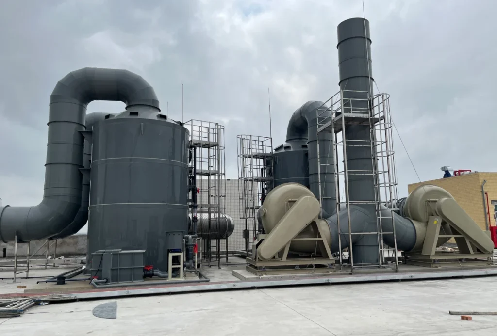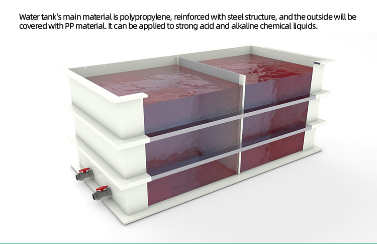
A rectangular plastic tank is a vessel whose four walls are flat plates. That is the whole of the definition, and it is also the whole of the problem, because a flat plate does not carry liquid pressure the way a curved one does. Every feature that makes the difference between a box that holds and a box that bulges — the ribs, the corner posts, the base frame, the plate thickness itself — exists to deal with that one geometric fact.
The gap between the two shapes is larger than most buyers expect. Take the same 12 mm plate and the same 2 m head of water. In a 2 m diameter cylinder the wall carries 1.635 MPa. In a flat panel spanning 2 m without support it carries 408.7 MPa — two hundred and fifty times as much. To bring the flat panel down to the cylinder’s stress you would need a plate 189.7 mm thick. That is not a detail of construction. It is a different structural regime.
So the design question for a rectangular plastic tank is never “how thick should the plate be”. It is “how short can the unsupported span be cut, and what carries the load once it has been cut”. This page answers that in order: what the object is and where it differs from the drum-shaped tanks it is usually confused with, what the load path has to do, how the span sets the plate with tables you can recompute, what happens at the corner and the floor joint, what the plan shape takes away, what the gallon numbers actually weigh, and when a round tank is still the better answer.
Key Takeaways
- A flat wall carries pressure in bending, not in tension, and bending stress rises with the square of the unsupported span. Halving the span quarters the stress; doubling it quadruples it. This one exponent explains ribs, posts and base frames.
- What sets the plate thickness is the spacing of the stiffeners, not the height of the wall. A 12 mm wall at 2 m head is good for a 280 mm span and fails at 2,000 mm.
- The load must close a four-link chain: panel, stiffener, post, base frame. A cylinder’s chain closes on itself; a box’s does not. A break at any link makes the other three useless.
- On the same footprint a box holds 27.3% more than the cylinder inscribed in it, while the wetted area per unit volume is identical. The extra volume is free in plate and paid for in structure.
- At a fixed volume and height the square plan is the lightest shape. A 4:1 plan carries 25.0% more perimeter, an 8:1 plan 59.1%, a 16:1 plan 112.5% — and perimeter times height is the wall area you have to buy and stiffen.
- Full-water weight goes through the floor and the base, not through the walls. 1,000 US gal of water is 3,785 L and 3.79 t. A rectangular plastic tank has to sit on a continuous, level support; it cannot stand on a ring the way a cylinder can.
What a Rectangular Plastic Tank Is, and Why It Is Not a Cylinder With Corners
Two different products are sold under the same words, and the difference between them is not size, not colour and not thickness. It is the process, and the process sets a hard ceiling on every dimension.
The Two Things the Market Calls a Rectangular Plastic Tank
The first is a rotomoulded polyethylene bin. A mould is charged with powder, rotated in an oven, and the plastic fuses into a one-piece seamless shell. It is a good product: no welds to leak, a smooth interior, and the consistency that comes from a mature mass-production line. It is also limited in a way that never appears on a datasheet, because the limit is the tool, not the resin.
The second is a fabricated vessel. Polypropylene sheet is cut, formed where necessary and welded into a box, with the structure — ribs, corner posts, base frame — welded or bolted on afterwards. This is the construction that a rectangular plastic tank for industrial duty almost always means, and it is the one this page is about. The materials differ too: a moulded bin is polyethylene, while a fabricated vessel is usually PP‑H, which holds its properties at temperatures and chemical exposures where PE starts to give up.
The standards treat them as separate subjects, and that is the clearest sign the split is real rather than a marketing distinction. ASTM D1998‑21, the specification that governs rotationally moulded polyethylene storage tanks, opens by limiting itself to “flat-bottom, upright, cylindrical tanks molded in one-piece seamless construction by rotational molding”, with capacities from 1,900 L (500 gal) up. There is no rectangular case in it at all. On the European side, EN 12573 is a series of four parts, and the parts are divided by shape: part 1 gives the general principles, part 2 covers the calculation of vertical cylindrical tanks, and part 3 covers the design and calculation of single skin rectangular tanks, with polypropylene named in its scope. A welded rectangular box is not a variation on a cylinder in either system. It is its own chapter. What that chapter buys and what it costs against the cylinder is the subject of cylinder versus box footprint.
The Size Ceiling That Moulding Runs Into
Rotomoulding has two hard limits, and both bite hardest on this shape.
The first is the tool. The mould has to fit in an oven, so the single-piece envelope is bounded by oven size, and a tank wall cannot be thicker in one place than another in any useful way. The second is worse for a box specifically: a stiffener cannot be welded onto a moulded wall after the fact. Any rib has to be moulded into the wall, which means its section, its spacing and its height are all frozen when the tool is cut. You cannot add a rib where the stress is, because the stress is not known until the tank is filled.
A fabricated vessel has neither limit. Ribs are cut from bar and welded on at whatever pitch and whatever depth the calculation asks for, at any point on the wall, including a deeper rib near the base where the pressure peaks. Large vessels can be shop-fabricated in sections and assembled on site. This is why the industrial answer for a wide, low, room-filling tank is a welded PP box in a support frame, and why the moulded catalogue stops where it does.
Rib pitch, corner posts and base frame all follow from that same calculation, and the build they belong to is described in how a box tank is fabricated from sheet.
Why the Campervan Searches Point Somewhere Else
Search for a box shaped water tank and you land in a different market: fresh water tanks for campervans and caravans, tool boxes that double as reservoirs, IBC totes, and bolt-together rectangular pools. The intent there is transport and storage of a few hundred litres in a vehicle, and the products are shaped to fit a wheel arch or a tray rather than to carry a liquid column.
Industrial buyers do not use that phrase. They search for a rectangular plastic tank, or for a rectangular poly tank when the material matters, and the distinction is worth keeping because the two searches want different objects. A vessel sized to a van is designed against vibration and slosh; a vessel sized to a room is designed against bending. If you arrived here from the campervan direction, the arithmetic below still applies, but the design pressures and the load cases will look unfamiliar.
For the material side of the same decision — which polymer survives which chemical at which temperature — the starting point is the polypropylene tank selection guide rather than this page. For the medium itself, the comparison of polymers against a chemical list sits in chemical storage tank materials.
The Load Path: Panel, Stiffener, Post, Base Frame
A cylinder has a property that is easy to overlook because it asks nothing extra of the structure: its load path closes on itself. Hoop tension in the wall is carried around the circle and returned to the same wall. There is no last link, no foundation that has to be right, and no reaction that has to be taken out of the structure and put somewhere else.
A box has no such property. Each wall is a flat plate loaded on one face, and the reaction has to be handed from the plate to something, and from that something to something else, until it reaches the floor. That handover is the four-link chain, and every link is loaded differently. A rectangular plastic tank fails at whichever link is weakest, not at whichever link looks thickest.
Link One: the Panel Bends
Consider a strip of wall one unit wide, spanning between two supports a distance b apart. The liquid pressure on it is uniform over the height of the strip, so the strip behaves like a beam under a uniform load. The bending moment at mid-span is M = q b²/8, where q is the pressure. The section modulus of a plate of thickness t is Z = t²/6, because the strip is one unit wide.
Put the two together and the stress is σ = 0.75 q b²/t². The b² is the important term. Nothing else in the design of a rectangular plastic tank matters as much, because nothing else gives you a factor of four for a factor of two.
Link Two: the Stiffener Shortens the Span
A stiffener is usually described as reinforcement, which makes it sound like extra material added for strength. It is not. A stiffener is a way of moving a support line into the middle of a plate, and its entire value is that it changes b from the wall width to the pitch.
The direction of the stiffener decides which span you shorten. Vertical stiffeners at a horizontal pitch s make the panel span horizontally over s. Horizontal stiffeners at a vertical pitch s make the panel span vertically over s. Either way the panel is the same calculation, and either way the number that matters is the spacing, not the wall height. A 3 m tall wall with ribs at 280 mm centres is a series of 280 mm panels stacked eleven high, and the plate does not care that the stack is tall.
Link Three: the Post Takes the Stiffener’s Reaction
Here is where the two arrangements stop being interchangeable, because the stiffener is now a beam itself.
If the stiffeners run vertically, each one spans the full height and delivers its load at two points: the base frame at the bottom and the top edge at the top. Because the pressure is zero at the top and maximum at the bottom, the load is triangular, and a triangular load on a simple span splits its reactions two to one. Two thirds arrives at the base and one third at the top. The maximum moment does not occur at mid-height but about 58% of the way down from the top, and it equals roughly 0.128 W L, where W is the total load on that stiffener and L is its span.
If the stiffeners run horizontally, each one spans the wall width instead, and its reactions land on the two vertical edges. Those edges are the corners, and at the corners there is nothing to land on unless a post is placed there. This is the reason a wide, low tank grows a visible post at each corner and often at intermediate positions, while a tall, narrow one may have none: it is the plan dimension that decides how many posts, not the height.
Link Four: the Base Frame Spreads It Into the Floor
The stiffeners deliver their reactions downward, and those reactions, plus the weight of the contents, have to reach the floor without overloading the plate that forms the bottom. A cylinder can be carried on a ring, because its shell is stiff enough to span between the ring and the base. A rectangular plastic tank cannot. Its floor plate is flat and flexible, and a flat plate supported only at its edges sags in the middle under a uniform load, which reverses the bending in the floor and pulls the wall-to-floor weld into a distortion it was not designed for.
The consequence is a requirement that appears in no catalogue and decides more installations than any other: the support under a rectangular plastic tank must be continuous and level over the whole base area — a steel frame with a deck, a plinth, or a slab — not a set of pads at four corners. The full weight is discussed in the capacity section, but the scale is worth stating early: 1,000 US gal of water is 3.79 t spread over the floor, and 20,000 US gal is 75.7 t.
Where the Top Edge Fits In
The top of the wall is the last support a panel can get, and it is the weakest one, because a top edge is a free edge with nothing above it to hold it straight. It receives the upper third of every vertical stiffener’s load, and it has to carry that load along the rim without deflecting outward.
That behaviour — how an open top resists the outward pull of its own contents, and what a rim, a lip or a flange does about it — is a subject of its own and is covered in how an open top tank handles its top edge. What matters here is only its position in the chain: it is the fourth support of the panel and the second support of the vertical stiffener, and a tank with a weak rim behaves as if its stiffeners were shorter at the bottom than at the top, which is exactly backwards from what the pressure wants.
Sizing the Wall: Why the Unsupported Span Sets the Plate
This is the part of rectangular plastic tank design that no catalogue, no retailer and no competitor page does, and it is the only part that turns a guess into a number. Everything below is arithmetic you can repeat on a calculator.
The Formula and Where It Comes From
Take a one-metre-wide vertical strip of wall, spanning between two supports a distance b apart. The pressure at the bottom of a water column of height H is q = ρ g H. With ρ = 1,000 kg/m³ and g = 9.81 m/s², that comes to 0.00981 H MPa — so 2 m of water is 0.01962 MPa, or about 2 tonnes per square metre.
The strip is a simple beam of span b under that uniform load, so its mid-span moment is M = q b²/8 per metre of width. Its section modulus per metre of width is Z = t²/6. Divide one by the other and the bending stress is:
σ = 0.75 q b² / t²
Two things follow immediately, and they are the two things that govern every decision on the page. First, b appears squared, so the span dominates. Second, t also appears as a square, so thickening the plate and moving the stiffener closer together are mathematically the same trade — they are two currencies for the same purchase. Plate is bought by the tonne; stiffeners are bought by the weld and by the floor space they occupy outside the tank. That is the only reason the trade is worth thinking about at all.
A word on the model. A simple-span strip is conservative: it ignores any continuity across the stiffener, and it ignores the restraint the floor joint gives at the bottom of the panel. Real designs use plate coefficients that credit both. Using the conservative strip here means every number below sits on the safe side of what a detailed analysis would give, which is the right direction for an article that a reader will check by hand. The general beam relation behind it — stress equals moment times distance from the neutral axis over second moment of area — is stated in the beam stress reference listed at the end.
The Pitch Table
Set the working allowable bending stress at 8 MPa. This is our own figure for the worked example, not a value quoted from any standard: the applicable design standard sets the method, and the actual allowable depends on the grade, the design life and the temperature-time history of the material. The sensitivity of the answer to this choice is shown further down, and the conclusion does not change across a wide range of it.
For each water depth, the table gives the maximum stiffener pitch b in millimetres that keeps the panel at or below 8 MPa, for four plate thicknesses. The pressure used is the worst case at the bottom of the wall, because a panel spanning vertically sees a triangular load but a panel spanning horizontally sees the worst pressure along its lowest course.
| Water depth H | q (MPa) | t = 10 mm | t = 12 mm | t = 15 mm | t = 20 mm |
|---|---|---|---|---|---|
| 1.0 m | 0.00981 | 330 mm | 396 mm | 495 mm | 659 mm |
| 1.5 m | 0.01472 | 269 mm | 323 mm | 404 mm | 538 mm |
| 2.0 m | 0.01962 | 233 mm | 280 mm | 350 mm | 466 mm |
| 2.5 m | 0.02453 | 209 mm | 250 mm | 313 mm | 417 mm |
| 3.0 m | 0.02943 | 190 mm | 228 mm | 286 mm | 381 mm |
Table 1 — Maximum stiffener pitch for a simple-span panel at 8 MPa allowable bending stress, water at 1,000 kg/m³, pressure taken at the bottom of each depth. Values are √(8 t² / 0.75 q) and can be recomputed directly.
Read any single row and the scale of the problem becomes obvious. At 2 m of water and 12 mm plate, the pitch is 280 mm. Not 1,400 mm, not 2,000 mm: 280 mm, which is roughly the width of a hand. That number is why a rectangular plastic tank looks the way it does — the ribs that appear to be decoration at regular intervals are the structure, and their spacing was set by the plate, not by an aesthetic preference.
Now compare the two shapes at the same thickness and the same head. A 12 mm wall at 2 m of water in a 2,000 mm diameter cylinder carries 1.635 MPa. The same 12 mm plate spanning 280 mm carries 8.01 MPa — already at the allowable. At 400 mm it carries 16.35 MPa, double the allowable, with no change in plate and no change in pressure.
Reading the Table the Other Way
The pitch is not always free to choose. Fabrication, access and the position of nozzles often fix it, and then the question inverts: given this spacing, what is the thinnest plate that will do? The same relation solves it directly, with t = √(0.75 q b² / 8).
| Water depth H | b = 250 mm | b = 300 mm | b = 400 mm | b = 500 mm |
|---|---|---|---|---|
| 1.0 m | 7.6 mm | 9.1 mm | 12.1 mm | 15.2 mm |
| 1.5 m | 9.3 mm | 11.1 mm | 14.9 mm | 18.6 mm |
| 2.0 m | 10.7 mm | 12.9 mm | 17.2 mm | 21.4 mm |
| 2.5 m | 12.0 mm | 14.4 mm | 19.2 mm | 24.0 mm |
Table 2 — Minimum plate thickness for a given pitch, same assumptions as Table 1. Compare the 12 mm column of Table 1 with the 300 mm column here: they meet at about 2.0 m of water, which is a useful consistency check on both.
The practical reading is that a pitch of 250 mm lets you use thin plate even at 2.5 m of water, while a pitch of 500 mm forces a plate twice as thick — and thick plate is not just heavier. It is harder to form, harder to weld without distortion, and much harder to weld to a thin floor plate at the base joint. Below about 8 mm, welding distortion starts to be a problem in its own right, so the useful band for a fabricated PP vessel runs from roughly 8 mm to 30 mm, and the pitch is chosen to land inside it.
How Sensitive This Is to the Allowable Stress
The weakest assumption in the whole calculation is the allowable stress, so it deserves a sensitivity check rather than a defence. Because b is proportional to the square root of the allowable, the response is gentle.
At 2 m of water with a 12 mm plate: an allowable of 5 MPa gives a pitch of 221 mm; 6 MPa gives 242 mm; 8 MPa gives 280 mm; 10 MPa gives 313 mm; 12 MPa gives 343 mm. Moving the allowable by more than a factor of two — from 5 to 12 MPa — changes the pitch by 55%, not by 140%. And in every one of those cases the pitch is still measured in hundreds of millimetres against a wall measured in thousands.
That is the point of the check. The exact value of the allowable decides how many ribs a tank has; it does not decide whether a tank needs ribs. Any argument about the correct allowable, and there are legitimate ones, happens inside a range where the design conclusion is already fixed.
Ten Stiffeners, or None
Put the arithmetic on a real wall. A rectangular plastic tank 3 m wide and 2 m deep, in 12 mm plate, at the 8 MPa working value, needs a pitch of 280 mm. Three thousand millimetres divided into bays no wider than 280 mm gives eleven bays and therefore ten intermediate vertical stiffeners, plus a post at each end.
Change the plate and the count moves gently: 10 mm plate needs twelve intermediate stiffeners, 15 mm needs eight, 20 mm needs six. Even at 20 mm — nearly twice the thickness — the wall still needs six ribs. The exponent that makes this so is the same b² that started the section: doubling the plate thickness only buys a pitch larger by a factor of two, and the wall is more than ten times wider than that.
Now the comparison. A vertical cylinder 2 m in diameter, holding the same 2 m of water in the same 12 mm plate, carries 1.635 MPa and needs no stiffeners at all. Not fewer. None. The whole of the difference between the two shapes is contained in that pair of numbers, and it is the honest answer to why industry builds so many round tanks: the rectangle buys floor area and pays for it with a structure the circle does not need.
The interior of that structure — how the rib itself is sized once the pitch is fixed — is worked in the pickling tank design article, which derives the same panel formula for a vessel whose duty adds corrosion to the load case. That derivation is not repeated here; what matters here is the consequence, which is that the rib becomes a beam in its own right and is usually the item that decides whether a PP-only structure is enough.
The Corner and the Base Joint: Where a Box Actually Fails
A panel calculation that comes out at 8 MPa against an 8 MPa allowable looks like a design that is exactly adequate. It is not, because the panel is rarely what fails. The two places a rectangular plastic tank actually gives trouble are the corner, where two panels meet at ninety degrees, and the wall-to-floor joint, where the vertical load path turns into the horizontal floor plate.
Two Panels Meeting at Ninety Degrees
At a corner, two plates arrive, each carrying bending moment from its own span, and their edges are welded to each other along a single line. That weld sees three things at once: in-plane shear from the two panels trying to pull apart, out-of-plane bending from each panel’s own curvature, and a stress concentration where the two edge conditions fight each other. None of that appears in the panel calculation, because the panel calculation assumes its edge is a support.
This is why a corner detail that is adequate on a small tank is not automatically adequate on a large one, even at the same pressure and the same plate. The panel stress depends on the span and the thickness; the corner stress depends on the span, the thickness, and the stiffness of the post or return that the corner is attached to. A tank whose panels are all at 6 MPa can still fail at a corner, and it is the corner that a visual inspection will notice last, because it is the most heavily built part of the outside and the most concealed part of the inside.
The Wall-to-Floor Weld Is a Fixed Joint, Not a Simple Support
The strip model that produced q b²/8 assumes a simple support, which means the panel is free to rotate at its edge. A welded wall-to-floor joint is not free to rotate. It is close to fixed, and that changes both members.
For the wall it is good news: rotational restraint at the base reduces the moment the wall has to carry in its lowest and most heavily loaded course. For the floor it is bad news, because the moment does not disappear. It is transferred into the floor plate, which now has to bend at its perimeter in addition to carrying the downward load of the contents. A floor plate designed as a flat plate under uniform load, without the perimeter moment from the wall, is under-designed at exactly the location where the two welds meet.
The practical consequence is that the floor plate of a rectangular plastic tank is usually thicker than a simple pressure calculation would suggest, and that the wall-to-floor weld is treated as a full-penetration joint rather than a fillet. It also explains why the continuous support requirement from the load-path section matters so much: a floor plate that is allowed to sag in the middle reverses its curvature, and a plate that was designed to be fixed at its perimeter and sagging nowhere is now being asked to work in two directions at once.
Why Corner Reinforcement Is Not Cosmetic
A corner reinforcement is often read as a sign of build quality, the way a heavier hinge is read as a sign of a solid door. It is not a sign. It is the member that takes the reactions the two panels deliver.
The tanks we fabricate carry corner reinforcement and external stiffener rings for exactly this reason, and the framing is stated openly on the rectangular PP storage tanks page: corner reinforcement, stiffener rings, and a PP-clad steel support frame for large vessels. The mechanism is worth stating plainly because the marketing language around it usually is not. A corner post shortens nothing: the panel span is still the pitch. What the post does is receive the two-thirds reaction from each vertical stiffener, carry it down, and deliver it into the base frame as a concentrated load. Take it away and the stiffeners are loading a weld that was never sized for a point reaction.
The Floor Plate at the Perimeter
Inside a loaded rectangular plastic tank, the floor plate is nearly unloaded in bending at its centre and heavily loaded at its edge. The liquid above presses down uniformly, which the continuous support underneath carries directly in compression; but at the perimeter, the wall’s fixed-end moment arrives as a line moment along the joint, and the plate has to resist it with a cantilever-like action towards the first stiffener or the first support beam beneath.
That is the opposite of the intuition a designer brings from a beam, where the middle is the critical section. It also means that an inspection which looks at the middle of the floor and finds nothing has learned very little, and that the perimeter — under the wall, along the joint, where the plate meets the frame — is where the detail has to be right. In a vessel intended to hold aggressive product, the same location is also the one where a pinhole will find its way out first, which is why the compounding choice for the joint matters as much as its geometry. The material side of that choice, including which polymers tolerate which media, is covered in chemical storage tank materials.
For duties where a single wall is not the containment answer at all — because the medium, the location or the regulation demands a second boundary — the design conversation changes shape rather than just getting thicker, and the arithmetic of an annulus is a separate subject: see double wall containment.
The Plan Shape: What a Long, Narrow Box Pays For
Once the volume and the height are fixed, one free choice remains: the shape of the plan. It looks like a purely practical decision — what fits in the room — and it is partly that. But the plan shape also fixes the perimeter, and perimeter times height is the wall area you have to buy, weld and stiffen. Nothing else in a rectangular plastic tank gives away so much for so little reason.
Square, Long and Narrow
Take 8 m³ at 2 m of depth. A square water tank at this volume is 2.00 m by 2.00 m, with a perimeter of 8.00 m. A 4:1 plan is 4.00 m by 1.00 m, perimeter 10.00 m. A 16:1 plan is 8.00 m by 0.50 m, perimeter 17.00 m. All three hold the same volume to the same depth, and all three would look reasonable on a drawing.
Square water tanks and long ones hold the same water; what differs is the wall. Most square plastic water storage tanks on the market are moulded bins, and a square plan is what a mould tends to produce, because a near-square tool uses an oven better than a long one. The trade uses several word orders for the same object — water tank square, square tank water, square water tanks plastic — and none of them describes a different vessel. The arithmetic below treats all of them as one shape, because they are.
The wall area, however, is not the same. Multiplied by 2 m of height, the square needs 16.00 m² of plate, the 4:1 needs 20.00 m², and the 16:1 needs 34.00 m² — more than double. And the penalty of a narrow plan is paid twice, because the stiffener length scales with the same perimeter while the stiffener span grows with the long wall.
What Each Step Away From Square Adds
The penalty rises steeply and then keeps rising. At a fixed 8 m³ and 2 m depth:
| Plan ratio (long : short) | Plan dimensions | Perimeter | Relative to square |
|---|---|---|---|
| 1 : 1 | 2.00 × 2.00 m | 8.00 m | — |
| 1.5 : 1 | 2.45 × 1.63 m | 8.16 m | +2.1% |
| 2 : 1 | 2.83 × 1.41 m | 8.49 m | +6.1% |
| 3 : 1 | 3.46 × 1.15 m | 9.24 m | +15.5% |
| 4 : 1 | 4.00 × 1.00 m | 10.00 m | +25.0% |
| 6 : 1 | 4.90 × 0.82 m | 11.43 m | +42.9% |
| 8 : 1 | 5.66 × 0.71 m | 12.73 m | +59.1% |
| 12 : 1 | 6.93 × 0.58 m | 15.01 m | +87.6% |
| 16 : 1 | 8.00 × 0.50 m | 17.00 m | +112.5% |
Table 3 — Perimeter of a rectangular plan holding 8 m³ at 2 m depth, as a function of the ratio. For a fixed volume V and depth H, the perimeter is 2(√(V r/H) + √(V/(H r))), which reaches its minimum at r = 1.
The first few steps are almost free: going from square to 2:1 adds 6.1% of the perimeter, which is often the right trade for a room that is twice as long as it is wide. Going from 4:1 to 16:1 adds another 70 percentage points, and that is rarely a decision anyone made on purpose.
Why Narrow Profile Tanks Exist Anyway
There is a legitimate reason for a long, narrow tank, and it is a single one: getting through a door. A narrow tank is bought when the route to the installation point is narrower than the tank would otherwise be — a standard doorway, a stairwell, a service corridor. In that case the narrowness is not a preference, it is an access requirement, and you pay for the access in plate, in stiffener length and in a longer base frame.
What is worth being honest about is the trade. On a long, narrow vessel the two long walls are the easy ones, because their span between vertical stiffeners is unchanged. The two short ends are the expensive ones, because their span is the tank’s depth and the stiffeners there have to work in the other direction. It is common to see a tall narrow tank with heavy end plates and a light long wall, and the reason is the plan ratio, not the fabrication.
L, T and S Shapes
Nothing in the rules requires a rectangle. Fold a plan and you get an L, a T or a stair shape, all of which occur where a tank has to wrap around a column, follow a wall or accept an existing opening. Each fold adds an external corner, and each external corner is a pair of panels meeting with no support behind them — the case discussed in the corner section, but now with both panels under load and neither of them acting as a buttress for the other.
The containment volume and the plate area also stop being simple multiples. An L-shaped plan holds less than its bounding rectangle by exactly the missing corner, so the volume on the drawing has to be measured from the actual plan rather than from the envelope. On vessels built this way, the arithmetic in this article applies panel by panel, and the panel that governs is the longest one, which is usually a fold rather than an edge.
When the geometry is the result of a spatial constraint rather than a volume requirement, a fabricated PP vessel is the only practical answer, because a mould cannot produce an L. The plating side of the same fabrication capability is set out on the pickling tank and electroplating tank page.
Capacity, Footprint and the Gallon Numbers
Most of the searching done around this shape is in gallons, and the arithmetic that answers it is simple. What is not simple is the gap between the number on the label and the number in the tank, and the weight that number implies for the floor.
Gallons, Litres and Weight
The US liquid gallon is defined as 231 cubic inches, which is 3,785.4 cm³ or 3.785 L. Water at close to room temperature has a density of about 1,000 kg/m³, so a litre weighs a kilogram and the conversion to tonnes is the litre count divided by a thousand.
| Nominal volume | Litres | Water mass | Pounds |
|---|---|---|---|
| 500 US gal | 1,893 L | 1.89 t | 4,173 lb |
| 1,000 US gal | 3,785 L | 3.79 t | 8,345 lb |
| 2,500 US gal | 9,464 L | 9.46 t | 20,864 lb |
| 5,000 US gal | 18,927 L | 18.93 t | 41,727 lb |
| 10,000 US gal | 37,854 L | 37.85 t | 83,454 lb |
| 20,000 US gal | 75,708 L | 75.71 t | 166,908 lb |
Table 4 — Water mass for nominal volumes, at 1,000 kg/m³ and 1 US gal = 3.785 412 L. Where the duty is not water, multiply by the specific gravity of the contents; a 1.8 SG liquor in a 1,000 gal tank is 6.82 t, not 3.79 t, and every structural number on this page scales with it.
The pounds column is the one that surprises people. A 20,000 gallon rectangular tank holds 166,908 lb of water, which is eighty-three tons, and that load is carried by the floor plate and the continuous support underneath it. It is not carried by the walls, and it must not be carried by a set of corner pads. If the support under a tank of that size is an uneven slab, the floor plate will find the high point and the wall-to-floor joint will be pulled out of shape long before the panels are anywhere near their allowable stress.
Nominal Volume and Working Volume
Every catalogue gives a nominal volume, which is the geometric capacity up to the top of the wall or to the overflow. The working volume is what a process can actually use, and it is smaller by the freeboard that has to be left above the highest working level.
The difference is not trivial at small heights. A 1,000 gallon box with a 2.0 m wall and 250 mm of freeboard holds 875 gallons at its working level — 12.5% less than the nameplate. Put the same 1,000 gallons in a 1.5 m high box and leave 200 mm, and the working volume is 867 gallons. The nominal number has not changed; the useful number has changed twice.
Two consequences follow for anyone comparing offers. First, the comparison has to be made at the same working volume and the same freeboard, or it is comparing two different tanks. Second, the freeboard is not slack that can be reclaimed: it is the space the top edge needs to resist the outward pull of the contents, and it is also the space that absorbs a level control failure. Reducing it to gain volume is a decision that moves load onto the weakest support in the structure.
Same Gallons, Different Boxes
The same nominal volume produces very different boxes depending on the height chosen, and the height is often the most constrained variable on site. A square 500 gallon water tank at 1.20 m of wall is 1.26 m by 1.26 m; the same volume at 2:1 is 1.78 m by 0.89 m, and at 4:1 it is 2.51 m by 0.63 m.
Those three boxes hold the same water and have very different spans. The square version has a 1.26 m wall span; the 4:1 version has a 2.51 m wall span, which is twice the panel span for the same volume and the same plate. Anyone who searches for a rectangle tank is usually after this exact trade, and the wording hides it: rectangular plastic water tanks carrying the same gallon figure on the label can differ by a factor of two in the span of their longest wall. The gallon count fixes the volume; the plan fixes everything else.
The same effect shows in the other direction when the height is allowed to change. A 1,000 gallon square tank is 1.95 m on a side at 1.0 m of wall, 1.59 m at 1.5 m, 1.38 m at 2.0 m and 1.12 m at 3.0 m. Taller means a smaller footprint and a shorter span, which is why height is usually the first thing to give if the room allows it — up to the point where the panel’s vertical dimension and the access to the top become the problems.
What the Calculators Do and Do Not Do
The tools that dominate the results for this shape take three inputs — length, width and depth — and return a volume. That is a correct answer to a geometry question, and it is the same calculation whether the vessel is a tank, a swimming pool or a rectangular prism water tank in a school textbook.
Three things those tools do not do, and all three are what a specification actually needs. They do not subtract freeboard, so the number they return is a nominal volume rather than a working one. They do not compute weight, so they say nothing about what the floor has to carry. And they say nothing about the structure the shape requires at that size, which is the entire subject of this page. A calculator can tell you that a box 2.51 m by 0.63 m by 1.20 m holds 500 gallons. It cannot tell you that the 2.51 m wall needs a different plate and a different stiffener pitch from the 0.63 m end.
Use the calculators for what they are good at — turning a footprint into a volume — and then bring the volume back here for the parts that decide whether the vessel holds.
Rectangular, Cylindrical, or Framed: Choosing for the Room
Everything above has argued that a box is expensive in structure. That is not an argument against boxes; it is an argument for knowing what you are buying. There are duties where a rectangular plastic tank is clearly right, duties where a cylinder is clearly right, and duties where the answer is a shape decision plus a frame.
When the Room Decides
The strongest case for a box has nothing to do with the tank and everything to do with the building. A box uses its footprint completely, so on the same area it holds 27.3% more than the largest cylinder that fits — a figure that comes only from the ratio of a square to its inscribed circle and is therefore independent of size. It sits flush against a wall where a cylinder leaves two crescents of dead space. It fits through a door that a wider cylinder cannot pass. It can be built into a corner, under a stair or around a column.
The trade is stated exactly: the extra volume is free in plate, because a square and its inscribed cylinder have identical wetted area per unit volume — the ratio works out to 2/H + 4/a for both. What the box does not give away in material, it pays back in stiffeners. That is the whole of the comparison, and anyone who tells you a box is simply more efficient, or simply weaker, is telling you half of it.
When the Process Decides
Mixing and settling are the two reasons a round tank wins on process grounds, and both come from the absence of corners. A cylindrical wall gives an even circumferential flow with no stagnation zone; a box has four corners where solids settle and where a impeller cannot reach. For a tank that will be agitated, or one where solids must not accumulate, the circle is the better vessel regardless of the room.
That process argument is the usual answer to the round-or-square question, and it is a good one. What it leaves out is the structural argument, which is that the circle is also the simpler vessel by a wide margin because it needs no stiffener chain at all — ten ribs and two posts against none, at the numbers already worked. When both arguments point the same way, the decision is easy; when the process wants a circle and the room demands a box, you are buying the box for the room and should be told what the room adds to the vessel.
When Containment Decides
If the medium or the location requires a second boundary, the shape question becomes secondary to the annulus question, because a double wall is not simply a thicker wall. Whether the gap is a sealed monitored chamber or an open equalising space changes the support detail, the shell thickness and the detection method, and the two philosophies cannot be combined. That subject has its own arithmetic and its own page: double wall containment.
When Drainage Decides
A flat-bottomed box drains from its lowest point and leaves nothing else, which is an advantage when the residue is harmless and a problem when it is not. A vessel that must fully empty, must be cleaned between batches, or must shed solids as it drains is better served by a conical floor, because gravity does the work that a flat plate cannot. The angle of that cone, and what it does to the wall loads at the transition, is covered in cone bottom tank.
Some duties need both properties, and then the answer is a hybrid: a rectangular plan with a sloped or dished floor section. That is a fabrication decision rather than a catalogue one, and it is the point at which the geometry should be drawn rather than selected.
A Short Decision Table
| What is fixed | Better shape | Why |
|---|---|---|
| Floor space, walls, doorways | Rectangular | +27.3% volume on the same footprint; flush against walls; passes a narrow opening |
| Agitation, settling, no dead zones | Cylindrical | Even circumferential flow; no corners for solids to collect |
| Full drainage, cleaning between batches | Conical bottom | Gravity drains what a flat plate retains |
| Second boundary required | Double wall, either shape | The annulus philosophy, not the plan, becomes the design driver |
| Large volume, limited headroom | Rectangular in a support frame | A wide, low box needs a continuous deck and a frame, since a flat floor cannot span a ring |
Table 5 — Shape selection against the constraint that is actually fixed. Note that only the first and last rows favour a box, and both of them are constraints of the building rather than of the process.
The rectangular plastic tanks we fabricate for this duty are PP storage tanks with corner reinforcement, external stiffener rings and, above a certain size, a PP-clad steel support frame — the four-link chain built explicitly rather than assumed. A vertical rectangular water tank is a normal request within that range, provided the plan ratio is known, because the ratio is what sets the plate and the rib count.
Frequently Asked Questions
Is a rectangular plastic tank weaker than a round one?
Yes, panel for panel, and by a large margin — but that is the wrong comparison. At the same plate thickness and the same head, a flat panel carries two hundred and fifty times the stress of a cylindrical wall spanning the same distance, which is why a rectangular plastic tank needs a stiffener chain a cylinder does not. The vessel is not weaker than a cylinder of the same mass; it is a vessel that spends its mass on a structure instead of on a curved shell. Compare them on total mass at the same duty, not on plate thickness.
How thick should the wall of a rectangular plastic tank be?
There is no single answer, because thickness is an output and the stiffener pitch is the input. The relation is t = √(0.75 q b² / σ), so a given thickness is only meaningful alongside the pitch it was chosen for. With 2 m of water and a 280 mm pitch, 12 mm lands at about 8 MPa. Halve the pitch and 8 mm would do. Double it and no practical plate is enough. Ask for the pitch and the plate together, or the number means nothing.
How far apart should stiffeners be?
Close enough that the panel between them stays within the allowable bending stress at the worst pressure on that panel — for 2 m of water and 12 mm plate, that is about 280 mm. In practice the pitch is also constrained from below by welding access: ribs spaced closer than roughly 250 mm stop being weldable with a decent fillet on both sides, so the useful range is narrow. That is why a wall at moderate depth comes out with ribs roughly every 250–350 mm and the number of ribs follows from the wall width.
Can a rectangular tank be made by rotomoulding at any size?
No. The single-piece envelope is bounded by the mould and the oven it has to fit in, and a moulded wall cannot have a stiffener welded onto it afterwards, so every rib must be cut into the tool. The specification that governs moulded polyethylene tanks reflects this by covering only “flat-bottom, upright, cylindrical tanks molded in one-piece seamless construction by rotational molding”, from 1,900 L (500 gal) up — there is no rectangular case in it. Beyond the moulded sizes, a rectangular plastic tank becomes a fabricated PP vessel by definition.
Does a rectangular tank need a steel frame?
Not always, but the threshold arrives earlier than most buyers expect, and it arrives through the ribs rather than the panels. A vertical stiffener at 280 mm pitch on a 3 m wide, 2 m deep wall carries 5.49 kN, and because the pressure is triangular it develops about 1.41 kN·m of bending over its 2 m span. At 8 MPa that needs a section modulus near 176,000 mm³. A 50 mm by 200 mm solid PP rib gives 333,000 mm³ and is comfortable; a 100 mm by 50 mm rib gives 41,667 mm³ and is not close. Depth, not width, is what buys section. Once the ribs have to be deep enough to intrude on the floor space around the vessel, a PP-clad steel frame outboard of the wall becomes the practical answer.
What does a 1000 gallon rectangular water tank actually weigh?
The water alone is 3,785 L and 3.79 t, or 8,345 lb. Add the vessel: a 1,000 gallon box at 2 m of wall is about 1.38 m square, and the PP sheet, the ribs, the posts and the frame will add a few hundred kilograms depending on the specification. Design the floor for the water plus the vessel plus a margin; the water is almost always the dominant term, and at 20,000 gallons it is 166,908 lb on its own.
Rectangular PP Tanks Built to Your Room, Not to a Mould
Three inputs settle most of a rectangular plastic tank. The first is the volume and the height that the room allows, because those two together fix the plan and the plan ratio, and the ratio sets both the plate area and the span. The second is the contents: specific gravity, temperature and whether the duty is water or an aggressive liquor, since every structural number scales with the density. The third is the support the site can actually provide — a level slab, a frame or a plinth — because a flat floor plate cannot span a ring and the detail has to be right before the plate is cut.
With those three we can fix the panel pitch, size the ribs, place the corner posts where the reactions arrive, and tell you whether the vessel needs an outboard steel frame or stands on its own base. If the plan is an L or a T rather than a rectangle, that is a fabrication question rather than a limitation, and it is worth sending as a sketch. Send the volume, the contents and the support condition and we will come back with a plate schedule, a stiffener pitch and a section through the base joint.
We have been fabricating industrial plastic equipment since 2009, which is 17 years. Our vessels use 5 mm to 30 mm polypropylene sheet, hydrostatic testing at 1.5 times design head, ultrasonic inspection of thick-section welds and a working tolerance of ±2 mm. We operate more than 40 production bases and offices, and hold ISO 9001, ISO 14001, CE, SGS and RoHS. Bodies and welds carry a 12-month warranty.
Note on the figures — The pitches, plate thicknesses, perimeters, volumes and masses on this page are our own hand calculations from the formulae printed beside each table, at the dimensions stated in each row, and any reader can repeat them. Pressure is q = ρ g H with ρ = 1,000 kg/m³ and g = 9.81 m/s²; bending stress is σ = 0.75 q b²/t² from a unit-width strip with M = q b²/8 and Z = t²/6.
Reactions are two thirds at the base and one third at the top for a triangular load on a simple span, with a maximum moment of 0.128 W L at 57.7% of the span from the light end. A square plan holds 4/π times the volume of its inscribed circle at identical wetted area per unit volume. The 8 MPa allowable bending stress is our own working value for these examples and is not quoted from any standard — the standard fixes the method, not the number. Section moduli are computed as b d²/6 on the stated bar dimensions.
- BSI — BS EN 12573-3:2000 — Welded static non-pressurized thermoplastic tanks: Design and calculation for single skin rectangular tanks (published 15 November 2000, current; scope descriptors include structural design, design calculations, welded joints, rectangular shape, polypropylene, polyethylene, PVC and PVDF; ICS 23.020.10).
- BSI — BS EN 12573-2:2000 — Welded static non-pressurized thermoplastic tanks: Calculation of vertical cylindrical tanks (published 15 November 2000, current; companion to part 3 in the same series, with part 1 covering general principles and part 4 covering flanged joints).
- ASTM International — ASTM D1998-21, Standard Specification for Polyethylene Upright Storage Tanks, §1.1 and §1.3 (active, last updated 13 August 2021; §1.1 covers flat-bottom, upright, cylindrical tanks moulded in one-piece seamless construction by rotational moulding, with capacities from 1,900 L (500 gal) up; §1.3 requires other relevant sources of standards to be consulted for service beyond its scope).
- UL Standards & Engagement — ANSI/UL 142, 11th edition, Steel Aboveground Tanks for Flammable and Combustible Liquids, §1.1 and §1.3 (dated 12 December 2025; §1.3 provides that each tank type may be fabricated in a combination of various shapes, cylindrical, rectangular or obround, and orientations, horizontal or vertical; §1.1 limits the standard to steel tanks for noncorrosive, stable flammable and combustible liquids with a specific gravity not exceeding 1.0 in aboveground applications).
- The Engineering ToolBox — Water Density, Specific Weight and Thermal Expansion Coefficients (pure water reaches its highest density, 1,000 kg/m³, at 4 °C; density at 10 °C is 999.70 kg/m³ and at 15 °C is 999.10 kg/m³).
- The Engineering ToolBox — Volume Units Converter (one US liquid gallon is 231 cubic inches, which is 3,785.4 cm³ or 3.785 litres).
- The Engineering ToolBox — Beams Supported at Both Ends with Continuous and Point Loads: Stress, Deflection, Formulas and Calculators (bending stress is expressed as σ = y M/I, with y the distance from the neutral axis and M the bending moment).