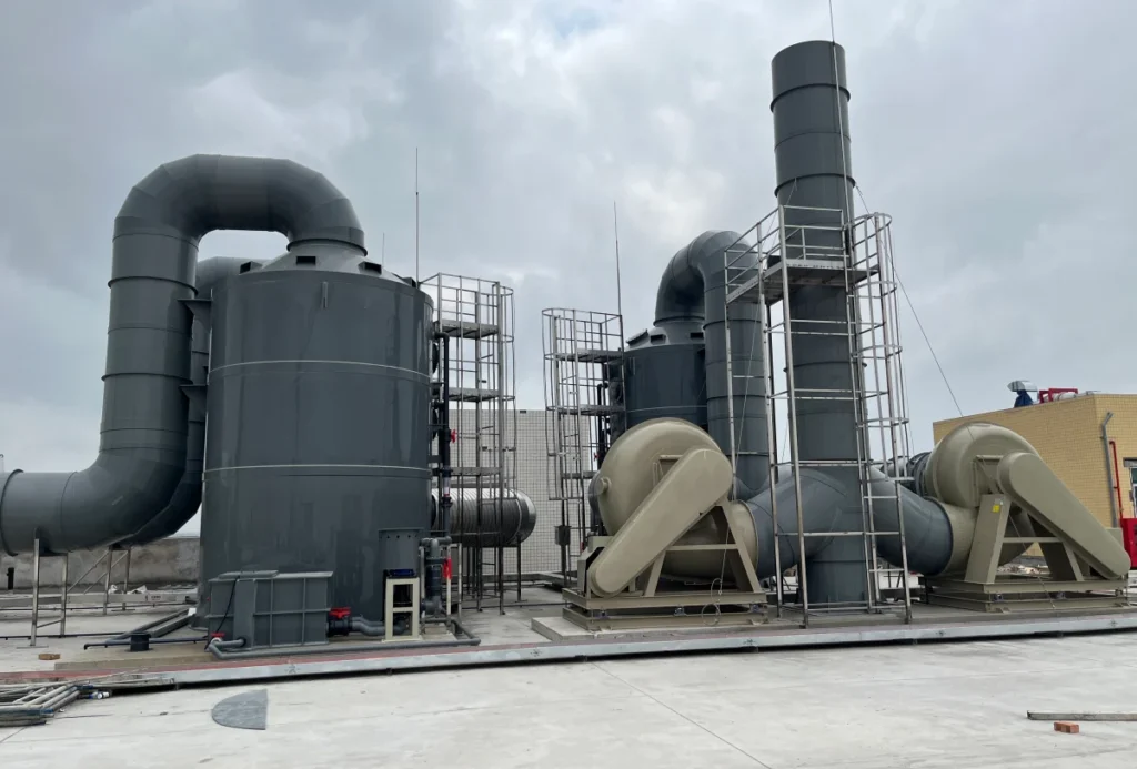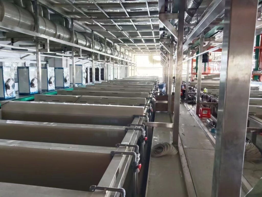
An electroplating tank is usually bought by the litre, and the litre is the least important number in the specification. The tank is the vessel of an electrochemical cell: a metal anode dissolves into it, a part immersed in it receives the metal, and a current passes through the solution between them. The dimensions come from the part and the anodes. The volume comes from how much metal the current will remove and how much heat it will add. And the tank’s second job, which the catalogue never shows, is to be the first stage of the rinse that follows it.
This page works through those three things in that order. The material comparison, the certification list and the configuration table belong to the PP electroplating tanks page and are not repeated here.
Key takeaways
- An electroplating tank is a cell, not a container: the part, the anodes and the electrolyte define it, and the tank is what holds all three in the right relationship.
- Internal dimensions follow from the part envelope, the anode clearance and the freeboard, not from a nominal volume.
- The volume follows from the current. Faraday’s law gives grams per ampere-hour, and a 288-litre nickel bath loses about 5 % of its metal to 1,000 ampere-hours.
- The same current heats the bath at P = V × I. A 100 A cell at 4 V adds 400 W, which lifts a 288-litre bath by 1 °C in about 50 minutes.
- Rinse tanks are part of the plating tank design because the process is defined as plating followed by a rinse. A two-stage cascade cuts the residual to about a fifth of one stage at the same water flow.
- The bath chemistry, not the temperature alone, decides the polymer, and the strongly oxidising baths are where polypropylene stops being the default.
- “Plated tank” returns planted aquariums and “rinse tank” returns parts washers. The words in the keyword list are not a specification.
What an Electroplating Tank Actually Is
The first thing to fix is what the object is. A tank that holds a chemical is a container; a tank that plates is one half of a circuit, and the difference changes every dimension on the drawing.
A cell, not a container
Electroplating needs three things at once: a cathode, which is the part being plated; an anode, which is the metal being deposited or an inert electrode; and an electrolyte, which carries the metal ions between them. The tank holds the electrolyte, positions the anode relative to the part, and carries the current into the solution through bus bars and anode hooks.
That is why a plating tank is shallow and open rather than tall and closed. The part has to go in and come out, the anodes have to hang beside it, the gas evolved at the electrodes has to leave, and an operator has to see the work. A tank designed as a storage vessel would fail all four.
The naming catches people out. In a plating cell the anode is the electrode that gives up metal and the cathode is the part that receives it, which is the reverse of how the two words feel when you read them on a battery. The consequence for the tank is that the anode is consumed and has to be replaced on a schedule, so the tank needs room for an anode that is getting shorter and for a fresh one that is longer.
Stray current is the other electrical fact the tank has to respect. Any metal path between the bus bar and something that should not be part of the circuit — the tank wall, a pipe, the building steel — becomes a parallel circuit, and the current that takes that path plates whatever it finds at the far end. That is how a tank develops a plated patch on its own rim, and how a steel support behind a plastic wall ends up corroded through.
The electrical role also constrains the material. Anything metal in contact with the bath is part of the circuit or is being attacked by it, so the tank’s job is to be the insulator that keeps the current where it belongs. A steel tank with a plastic lining does that job until the lining is damaged; a thermoplastic tank does it by construction.
The line around it: clean, pickle, plate, rinse
No plating tank works alone. The part arrives oily, scaled or oxidised, and it leaves wet with a film of the bath. Between those two states it passes through cleaning, pickling, plating and rinsing, and each of those steps is a tank.
The regulation that governs plating wastewater treats the sequence as a unit. It defines an operation as any step in the electroplating process in which a metal is electrodeposited on a basis material and which is followed by a rinse, and it includes alkaline cleaning, acid pickling, stripping and colouring when each is followed by a rinse. The rinse is not an afterthought in that definition; it is what makes the step a step.
Two consequences follow for the tank specification. The first is that the plating tank and its rinse tank are bought together, because the rinse load is set by what the part carries out of the plating tank. The second is that the pre-treatment tanks belong to the same line but not to the same design problem, and the acid pickling step has its own article — the pickling tank guide covers the acid side, its temperatures and its ventilation.
What this page is actually about
Material selection for a plating tank is a real question and has its own page. The question here is the geometry and the arithmetic: how big the tank has to be, how much solution it has to hold, how fast the current will change that solution and heat it, and how the rinse that follows sets the second tank.
The rest of this page covers the part-to-tank dimension chain, the Faraday arithmetic behind the volume, the heat load, the rinse cascade, the material and mist questions, and the six inputs a fabricator needs to quote.
The Tank Is Sized by the Part and the Anodes
The internal dimensions of a plating tank are fixed by what has to go inside it and what has to hang beside it. Volume is an output of those dimensions, not an input.
Immersion depth and the part envelope
The part has to be fully immersed, with clearance below it for the solution to circulate and clearance above it so that the top edge is not at the surface. The liquid depth is therefore the part’s vertical extent plus those two clearances.
The clearances are not arbitrary. Too little below the part and the deposit at the bottom edge is starved of fresh solution; too little above and the top edge sits in the meniscus, where the current density is different and the deposit is thin. A common arrangement is 100 mm below and 100 mm above, which is a working figure rather than a rule, and it should be adjusted for a part whose geometry concentrates current at one end.
The part envelope also sets the length. The ends need clearance for the rack and for the operator’s handling, and a part that has to be turned during the cycle needs enough length to turn in.
Anode spacing and the working width
The width is where the plating problem is most visible. Anodes hang on both sides of the part, and the distance between an anode and the nearest part surface decides how evenly the deposit forms.
Move the anodes further out and the current has to travel further through the solution, which raises the voltage needed for a given current and throws more of the power into heating the bath. Move them closer and the deposit concentrates on the surface facing the anode, leaving the back and the recesses thin.
The practical compromise is a clearance of the order of 150 mm on each side, which includes the anode, its bag and the space the bag needs to breathe. That is a starting point for a flat part; a part with deep recesses needs the anodes positioned to see into them, which usually means more than two anodes and a wider tank.
Freeboard, the rim and the fume path
Above the liquid line there is freeboard: the height between the working level and the rim. It exists for three reasons. It contains the splash and the wave from a part being lowered. It gives the mist somewhere to be collected before it reaches the room. And it gives the tank enough stiffness at the rim to stay straight when it is full.
The freeboard is also the fume path. A plating tank is open, and the gases and mist that leave the bath rise through that opening. Side-draft exhaust draws across the freeboard, so the freeboard height and the exhaust slot are designed together: a deeper freeboard gives the exhaust more to work with, and a shallow one puts the mist into the room before it can be captured.
Rack, barrel or reel-to-reel
The chain above assumes rack plating, where the part is fixed to a frame and lowered in. Rack plating gives the clearest dimension chain because the part sits still, and it is the form most job shops mean when they ask for a plating tank. The rack itself counts as part of the envelope: its frame, its contact hooks and the space the operator needs to hang it all add to the length and the height.
Barrel plating changes the geometry completely. The parts go into a perforated barrel that turns in the bath, so the dimension that sets the tank is not the part but the barrel’s swing diameter, plus clearance for the barrel to rotate without touching the anodes or the wall. The liquid depth has to cover the barrel at every angle of rotation, which usually makes a barrel tank deeper than a rack tank for the same part size.
Reel-to-reel plating, used for strip and wire, makes the tank a long shallow channel that the strip passes through on rollers. Here the dimension that matters is the pass length, which sets the dwell time in the bath, and the width is barely more than the strip. The three forms share the clearance logic but not the numbers, and a fabricator quoting from a part drawing alone will size the wrong one.
From envelope to internal dimensions
Putting the four clearances together gives a chain that runs from the part to the drawing. Take a part 600 mm long, 300 mm wide and 400 mm deep, with 100 mm clearance at each end, 150 mm of anode clearance at each side, 100 mm below the part, 100 mm of liquid above it, and 150 mm of freeboard.
The internal length is 600 + 200 = 800 mm. The internal width is 300 + 300 = 600 mm. The liquid depth is 400 + 200 = 600 mm, and the tank height is 600 + 150 = 750 mm. The working volume is 0.8 × 0.6 × 0.6, or 0.288 m³ — 288 litres.
That 288 litres is not a chosen number. It is what the part produces, and the same chain run for a smaller or a larger part gives the other two rows of the table below.
| Part envelope (L × W × D) | Internal L × W | Liquid depth | Tank height | Working volume |
|---|---|---|---|---|
| 300 × 150 × 200 mm | 500 × 450 mm | 400 mm | 550 mm | 90 L |
| 600 × 300 × 400 mm | 800 × 600 mm | 600 mm | 750 mm | 288 L |
| 1,200 × 400 × 600 mm | 1,400 × 700 mm | 800 mm | 950 mm | 784 L |
Note on the figures — the chain is 100 mm end clearance, 150 mm anode clearance each side, 100 mm below the part, 100 mm of liquid above it and 150 mm of freeboard. These are working clearances chosen for the example, not values from a standard; a different part geometry moves them.
The Volume Follows the Current, Not the Part
Once the tank exists, the next question is how much solution it has to hold. The answer comes from electrochemistry rather than from geometry, and it is one of the few places in tank design where the arithmetic is exact.
Faraday, in grams per ampere-hour
Every mole of electrons carries a fixed charge, the Faraday constant, 96,485 coulombs. A metal with valence n needs n moles of electrons to deposit one mole of atoms, so the mass deposited by a current I over a time t is M × I × t / (n × F), where M is the molar mass.
For an ampere-hour, t is 3,600 seconds, and the expression collapses to a single number per metal. Nickel, with a molar mass of 58.69 and a valence of 2, gives 58.69 × 3,600 / (2 × 96,485), or 1.095 grams per ampere-hour. Copper gives 1.186, zinc 1.220, and chromium 0.323.
Chromium is the interesting one. Its valence in a chrome bath is 6, so six electrons are needed per atom and the same current deposits less than a third of the metal that nickel would. That single fact explains why a chrome tank of the same area runs at a much higher current for a comparable thickness, and why it heats faster.
The arithmetic gives the theoretical maximum, and real baths fall short of it because not every electron ends up reducing a metal ion. Some of the current goes into evolving hydrogen at the cathode, and some is lost to secondary reactions in the bath. The fraction that does the plating is the current efficiency, and it is the reason a plated part can be thinner than the calculation says. A bath running at 95 % efficiency deposits 95 % of the table’s mass for the same charge.
The efficiency is not a constant. It moves with the bath’s metal concentration, its temperature, its agitation and the current density, which is why the same bath can plate consistently for months and then drift. It also sets what the anode has to do: if the anode dissolves at the same rate the cathode deposits, the bath’s metal content stays level, and if it does not, the bath slowly gains or loses metal and needs topping up or diluting. A chrome bath uses insoluble anodes, so all of its metal has to be added as a salt — which is why chrome baths are the ones that most often arrive at the tank with a chemical make-up problem attached.
What 1,000 ampere-hours takes out of the bath
The same number works in the other direction: it tells the plant how much metal leaves the solution. A 288-litre nickel bath at 75 grams of nickel per litre holds 21.6 kilograms of metal. One thousand ampere-hours at 1.095 g/Ah removes 1.095 kilograms, which is about 5 % of the bath’s nickel.
That 5 % is the reason a plating tank has a minimum volume rather than only a maximum. A bath with very little metal in it swings in concentration with every rack, and the deposit thickness becomes a function of how recently the bath was analysed. The volume buys stability, and the arithmetic says how much stability a given tank buys.
It also gives a maintenance number. If the bath is analysed and topped up on a schedule, the schedule can be set from the ampere-hour meter rather than from the calendar: the metal removed is proportional to charge passed, so a bath at 10 % depletion is a known number of ampere-hours away, not an unknown number of weeks.
That is the practical reason a rectifier with an ampere-hour totaliser is worth having. The totaliser turns the bath into a bookkeeping problem: each shift logs the charge it passed, the metal removed follows from the table, and the make-up addition follows from the difference. Without it, the same information has to come from bath analysis, which is slower and which tells you the concentration now rather than the rate it is falling.
| Metal | Valence | Grams per Ah | Micrometres per Ah per dm² |
|---|---|---|---|
| Nickel | 2 | 1.095 | 12.3 |
| Copper | 2 | 1.186 | 13.2 |
| Zinc | 2 | 1.220 | 17.1 |
| Chromium | 6 | 0.323 | 4.5 |
| Silver | 1 | 4.025 | 38.4 |
Note on the figures — grams per ampere-hour = molar mass × 3,600 ÷ (valence × 96,485). The thickness column divides that mass by the metal’s density — nickel 8.90, copper 8.96, zinc 7.14, chromium 7.19, silver 10.49 g/cm³ — and spreads it over 0.01 m². Real baths run at less than 100 % current efficiency, so the thickness achieved is lower than the table.
The bath heats at P = V × I
The same current that deposits metal also heats the solution. The power dissipated in the cell is the cell voltage multiplied by the current, and for a plating bath most of that power ends up in the liquid.
Take the 288-litre tank from the previous section running at 100 amperes and 4 volts. The heat input is 400 watts. Water needs 4,186 joules to raise one kilogram by one kelvin, so 288 kilograms needs about 1.21 megajoules for one kelvin, and at 400 watts that takes about 3,000 seconds — fifty minutes.
Fifty minutes per kelvin is the number that decides whether the tank needs cooling. A bath that runs for a shift at that current gains several kelvin from the current alone, before any heater is counted, and a bath that must hold a set point within a degree or two cannot do it without removing that heat.
The geometry feeds back into this. A wider anode spacing raises the cell voltage for the same current, and the power is the product of the two, so a tank made generous for evenness pays for it in heat. That is the trade the anode clearance is really making.
Two corrections keep the estimate honest. The bath is not pure water: a concentrated nickel or copper solution has a specific heat somewhat below water’s, so the real temperature rise per kilowatt-hour is a little larger than the calculation gives. And an open tank loses heat by evaporation, which is not a small term at plating temperatures — it is the reason a bath can sit at temperature overnight without a heater running.
The two corrections push in opposite directions, which is why the estimate is useful as a screening number rather than a design number. If the joule heat is small compared with the heat the tank loses to the room, the tank will settle at its own temperature and needs only a trim heater. If it is larger, the tank needs a cooling duty and that duty has to be sized on the real numbers.
Temperature Is the Second Design Load
Plating baths run at different temperatures, and the tank has to hold the one its process needs while the current is pushing heat into it from below.
Bath temperature is a process value, not a tank value
The temperature a bath runs at comes from the chemistry and from what the deposit needs, and it ranges from ambient for some acid copper baths to well above ambient for nickel and chrome. The tank does not set that value; it has to survive it and, where necessary, hold it.
The important consequence is that the tank has two thermal duties rather than one. It has to be chemically and mechanically sound at the working temperature, which is a material question, and it has to be able to hold that temperature against the current’s heat, which is an equipment question.
Where the process needs a tight band, the band is a control problem. A bath that must stay within a degree needs a sensor, a controller and a heat exchanger sized for the largest disturbance, and the largest disturbance is usually the current, not the room.
Heating, cooling and where the heat exchanger sits
Heating is usually done by immersion heaters in the tank or by an external heat exchanger with a circulation pump. Immersion heaters are simple and put the heat where it is needed; they also take up tank volume and are the component most exposed to the chemistry, which is why their sheath material matters as much as the tank’s.
Cooling is the part that gets left out of the budget. It is needed whenever the current’s heat exceeds the losses to the room, which on a busy line is most of the time. An external chiller and heat exchanger, or a cooling coil in the tank, has to be sized for the joule heat calculated above plus the heat from any immersion heater that is running.
Where the exchanger sits changes the tank drawing. An external exchanger needs a suction and a return connection, and the return should not be aimed at the part, because a jet of solution at a different temperature changes the local deposition rate. A coil in the tank needs space beside the anodes and has to be arranged so that it does not shield the part from the anode.
Sizing the exchanger is an energy balance rather than a rule of thumb. The duty is the joule heat from the cell, plus the heat from any immersion heater that is running, minus the heat the tank loses through its walls and its open surface. In a tank that is heating up, all three terms matter; in a tank at steady state, the joule heat and the losses set the duty and the heater only trims.
The balance also tells you when a heater and a cooler are fighting each other. A tank with a heater sized for a cold start and a cooler sized for the current will, if both are controlled from the same sensor, spend the shift adding heat and removing it. The fix is a dead band in the controller and a cooling duty sized for the current alone, not for the current plus a heater that should have switched off.
What the tank material has to survive
The material question is usually stated as chemical resistance, and it is really a question of chemical resistance at temperature, under current, for years. Polypropylene homopolymer has a melting range in the 160 to 165 °C band and a softening temperature around 152 °C, so a bath at 60 °C is well inside its thermal capability; the limiting factor is the chemistry rather than the heat.
That is why the same polymer can be right for one bath and wrong for another at the same temperature. The compatibility question is set out with the material data in the polypropylene tank guide, and the strongly oxidising baths are the ones where polypropylene stops being the default.
The Rinse Is Part of the Tank Design
The rinse tank is usually specified by somebody else, later, and that is a mistake. The rinse load is set by the plating tank, and the arithmetic that sizes it is as exact as the Faraday calculation.
Drag-out is the load the rinse has to remove
When a rack comes out of the plating tank it carries a film of solution with it. That film is the drag-out, and it is the only thing the rinse has to deal with: the rinse does not remove what is on the part by magic, it dilutes the film and carries it away.
Drag-out depends on the part’s shape, its surface, how fast it is withdrawn and how long it drains over the tank. A flat sheet drains almost dry; a basket of small parts carries much more. Because it varies so widely, the rinse is usually designed on a measured or assumed drag-out rate rather than on a formula.
What matters for the tank is that drag-out is a volume per hour, and the rinse tank’s job is to dilute that volume into a much larger flow of water. The ratio of the two sets everything.
Drag-out can be measured with nothing more than a measuring cylinder. Take a part, let it drain over the plating tank for the same time it drains in production, then let it drain over a clean container and measure what comes off. Do that for the parts that matter and you have the figure the rinse is designed on, in millilitres per part, which becomes litres per hour once the throughput is known.
The measurement is worth doing because the difference between a flat sheet and a basket of small parts is large. A basket holds solution in the gaps between the parts and in the mesh, and it drains slowly, so its drag-out per kilogram can be many times the sheet’s. A rinse designed on the sheet and applied to the basket will run well above its residual target.
One tank, or a cascade
In a single rinse tank with a continuous water flow, the concentration in the tank reaches a steady state where the metal carried in equals the metal carried out. If the drag-out is d litres per hour and the rinse water flow is q litres per hour, the steady-state concentration is the bath concentration multiplied by d / (d + q).
With a drag-out of 1 litre per hour and a flow of 20 litres per hour, the ratio is 1/21, or 4.8 % of the bath concentration. That is one tank doing one dilution.
Two tanks in counterflow do much better. The second tank overflows into the first, so the part meets the cleanest water last and the dirtiest first. The steady-state ratio for n stages is the single-stage ratio raised to the power n: with two stages, (1/21)², or 0.23 %; with three, 0.011 %.
That is why a cascade exists. It reaches a lower residual with the same water flow, or the same residual with far less water, and the second tank costs less than the water it saves over a year.
There is a second lever in the same expression, and it is the one that gets ignored. The residual depends on the ratio of flow to drag-out, not on either alone. Halving the water flow roughly doubles the residual of a single stage, from 4.8 % to 9.1 % in the table below, because the ratio q/d falls from 20 to 10. The same cut applied to a three-stage cascade moves its residual from 0.011 % to 0.075 % — a larger factor, but still a negligible absolute figure.
That is the argument for adding a stage rather than a bigger pump. Extra water buys dilution linearly; an extra stage buys it exponentially, and the water it saves is water that does not have to be treated before discharge.
| Rinse stages | Residual at q/d = 10 | Residual at q/d = 20 |
|---|---|---|
| 1 | 9.1 % | 4.8 % |
| 2 | 0.83 % | 0.23 % |
| 3 | 0.075 % | 0.011 % |
Note on the figures — residual = (d / (d + q))n, where d is drag-out and q is rinse water flow, both in litres per hour. It assumes perfect mixing in each tank and no carry-over between stages; a real cascade sits a little above the table.
Where the rinse tank sits on the line
The rinse tank’s position is fixed by the process: it comes immediately after the plating tank, and the drain time over the plating tank is the first thing that reduces drag-out. A rack that is lifted slowly and held over the tank for a few seconds carries less into the rinse than one that is pulled out and swung across the floor.
The tank itself is usually smaller than the plating tank, because the part only has to be dipped rather than held through a full cycle, and it is often a cascade of two or three compartments in one vessel. That is a tank-design decision: one shell with internal weirs is cheaper than three shells with connecting pipework, and it keeps the counterflow path short.
Where the rinse water has to be treated before discharge, the cascade also reduces the treatment load, because the same dilution is achieved with less water to treat. That is the point where the rinse tank design meets the wastewater design, and it is worth settling both at the same time.
Two alternatives sit in front of the first rinse tank and are often cheaper than adding a compartment. A drag-out rinse is a small still tank, not fed with water, that the part enters first; it collects most of the drag-out at close to bath strength and that solution is returned to the plating tank. A spray rinse plays water over the part as it leaves, which knocks off the film before it has a chance to dry.
Both reduce what the cascade has to do, and both change the tank list. A drag-out rinse is a small tank with a return connection to the plating tank; a spray rinse is a chamber between two tanks with its own drain. Neither is a plating tank, and neither appears in a quotation for one, which is why the rinse decision belongs in the same conversation as the tank decision.
Material, Mist and Containment
Three things sit around the plating tank rather than inside it, and all three are decided when the tank is specified.
The bath decides the polymer
The polymer is chosen for the bath, at its temperature, for the life of the line. Polypropylene, PVC, PVDF and FRP with a vinyl ester resin all appear in plating shops, and the choice between them is a compatibility question rather than a cost question.
The pattern is that the more oxidising the bath, the less the polyolefins are the default. A chromic acid bath is the case that most often rules polypropylene out, and the resistance data for the concentration and temperature actually in use has to be checked before the tank is ordered. Where polypropylene is the answer, the wall is the barrier at full thickness, with no lining to blister and no interface to corrode.
The three alternatives each answer a different part of the problem. PVC is a good fit for some acid baths at moderate temperature and is easy to weld, but its temperature ceiling is lower than polypropylene’s. PVDF costs more and is chosen where the temperature or the chemistry is beyond what polypropylene will take. FRP with a vinyl ester resin is chosen for large tanks and for baths where a thermoset surface is preferred, and it brings its own questions about the resin grade and the liner thickness.
None of those four is universally right, and a shop that standardises on one polymer will eventually have a bath it cannot put in its standard tank. The compatibility check is per bath, at the working temperature, and it is the one step in the specification that cannot be inherited from the previous project.
The temperature ceiling is a separate check. Polypropylene homopolymer softens around 152 °C, so a bath well below that is inside its range; the question is whether the chemistry allows the polymer at all.
Hexavalent chromium mist
A chrome bath evolves a mist that contains hexavalent chromium, and the exposure limit for that is 5 micrograms per cubic metre as an eight-hour time-weighted average, with an action level at half that. The limit is low, and it makes the tank’s open top a ventilation problem rather than a convenience.
The controls are a combination: a mist suppressant in the bath, side-draft exhaust across the freeboard, and a mist eliminator or scrubber before the air leaves. Each of them depends on the tank geometry, which is why the freeboard height and the exhaust slot are designed together with the tank rather than after it.
The suppressant works by lowering the surface tension of the bath so that the bubbles bursting at the surface throw less mist. It is a bath addition rather than a tank feature, but it only works if the tank’s freeboard gives the foam time to collapse before the air leaves, which is another reason the freeboard is not just splash protection.
The limit is a time-weighted average over eight hours, and that matters for how the tank is used. A bath that is idle for most of the shift and busy for one hour can pass the average while putting an operator through a short, high peak. The exposure limit does not make the peak harmless, and the controls that reduce the peak are the ones at the tank — the exhaust slot and the suppressant — rather than anything downstream.
Cyanide baths add a second constraint: their ventilation must not mix with acid fumes, because the mixture can generate hydrogen cyanide. That is a ductwork and room-layout decision, but the tank’s position in the room is part of it.
Bunds and the floor
A plating tank holds a solution that must not reach the drain untreated, and the floor around it is the last barrier. A bund — a liquid-tight kerb around the tank or the line — catches a leak or a spill before it spreads, and it is far cheaper to build with the line than to add afterwards.
Where the tank itself has to contain a failure, the double-wall arrangement does it without using floor space; the annulus design is covered in the double wall tank article. A bund and a double wall answer different questions, and a line may need one, the other or both.
Where the solution is a hazardous waste, containment becomes a regulatory requirement rather than a preference. The RCRA container standard requires a containment system able to hold 10 % of the volume of the containers or the volume of the largest container, whichever is greater. It governs hazardous waste container storage areas rather than every plating tank, but the principle is the same one a bund applies.
Bus bars and the tank’s electrical role
The current enters the tank through bus bars, anode hooks and cathode bars, and every one of those is a place where a plating tank differs from a storage tank. The tank has to carry them, insulate them from each other, and keep them out of the solution except where they are meant to be in it.
The practical details are unglamorous and decisive. A bus bar that sags into the bath is a short circuit and a contamination source. An anode hook that is not insulated where it crosses the tank rim loses current to the rim. A cathode bar that is not level puts the part at an angle, and an angled part plates unevenly.
None of that is chemistry. It is the reason the tank drawing has to show where the bars sit, how they are supported and what they are insulated with — and it is the part of the specification most often left to the electrical contractor.
Bus bar sizing is a voltage-drop question before it is a current-carrying one. A bar that is generous in cross-section loses little voltage along its length, so the rectifier setting is close to what the cell actually sees; a bar that is marginal loses a volt or two over a few metres, and that loss appears as heat in the bar rather than as plating current in the tank. The practical check is to measure the drop between the rectifier and the tank under load, not to rely on the bar’s nominal rating.
The connections matter as much as the bar. A bolted joint that has loosened or oxidised has resistance, and resistance in a high-current circuit means heat at the joint and a lower current at the part. That is a maintenance item rather than a design one, but it is the reason a plating line that has “gone slow” is sometimes a line with a dirty joint rather than a bath out of balance.
Specifying an Electroplating Tank
The specification reduces to six inputs, and the first two decide the dimensions while the next two decide the volume.
The six inputs
The first is the part envelope: the largest length, width and depth that has to be immersed, and whether it has to be turned. The second is the anode arrangement: how many anodes, on which sides, and whether inert electrodes are needed.
The third is the bath: its chemistry, its concentration, its operating temperature and its specific gravity. The fourth is the electrical duty: the current, the voltage and the ampere-hours per shift, which together give the heat and the metal consumption.
The fifth is the rinse: whether the line needs one tank or a cascade, and the water flow available. The sixth is the site: the floor space, the headroom, the bund and the exhaust arrangement.
Each of the six has a failure mode when it is left out, and the failure modes are predictable. Without the part envelope the tank is sized on a nominal litre figure and the part does not fit. Without the anode arrangement the width is a guess and the deposit is uneven on one face. Without the bath chemistry the polymer is chosen from the previous project and the tank fails in the first year.
Without the electrical duty the volume has no basis, the heat is not budgeted and the bath either overflows its temperature band or needs a cooler added later. Without the rinse the second tank is bought separately and the cascade does not line up. Without the site the tank arrives and does not go through the door, or it fits but the exhaust has nowhere to run.
None of those is a hard question. They are all answers the customer already has, and the quotation gets faster when all six arrive together.
The material question
Once the bath and the temperature are fixed, the polymer is usually decided by the compatibility data, and the tank construction follows the standard for welded thermoplastic vessels, which separates vertical cylindrical from rectangular work. Moulded polyethylene is not the route for a plating tank: the standard for polyethylene upright storage tanks starts at 1,900 litres and caps continuous service below 66 °C, and a plating tank is usually smaller and may be hotter.
Two constraints are worth repeating. Where the bath is potable-adjacent, which is rare in plating but common in the rinse that follows it, the wetted parts need health-effects certification. And where the solution is an acid, the concentration band decides the material before the volume does, which is the subject of the acid storage tank article.
What we build
We fabricate PP-H plating tanks from 5 mm to 30 mm sheet, in rectangular and cylindrical forms, with the anode and cathode bar supports, the overflow weir, the drain and the level connections built in during fabrication. Where the line needs a cascade, the compartments and weirs are part of the same shell. Where the connections have to be specified, the poly tank fittings page covers the three routes through a wall.
For a quotation we need the six inputs above, plus the delivery location. Send them and the reply is a dimensioned drawing and a price. The full range and the configuration parameters are on the PP electroplating tanks page, and where the plating line needs a bulk chemical store behind it, the chemical storage tank guide covers that vessel.
Where the bath is topped up automatically from a made-up solution rather than by hand, the vessel that holds and meters it is a chemical dosing tank, and it is sized from the dose rather than from the part. The two vessels sit at opposite ends of the same line and are sized by different arithmetic.
Frequently Asked Questions
How do I size an electroplating tank?
Start from the part: add end clearance for handling, anode clearance on each side, clearance below and above the part, and freeboard. That gives the internal length, width and height, and the volume follows. Then check that the volume is large enough for the ampere-hours the bath will pass.
How much metal does 1,000 ampere-hours remove?
It depends on the metal. At 100 % current efficiency, 1,000 Ah removes 1.095 kg of nickel, 1.186 kg of copper, 1.220 kg of zinc or 0.323 kg of chromium. Real baths run below 100 %, so the actual figure is slightly lower.
Why does my plating bath get hot?
The cell dissipates power equal to voltage times current. A 100 A cell at 4 V puts 400 W into the bath, which raises 288 litres by about 1 °C every 50 minutes. If the bath must hold a set point, that heat has to be removed by cooling.
How many rinse tanks do I need?
As many as the residual target requires. One stage at a water-to-drag-out ratio of 20 leaves about 4.8 % of the bath concentration; two counterflow stages leave 0.23 %; three leave 0.011 %. Each additional stage costs a compartment and saves water.
Can polypropylene be used for chrome plating?
Not usually. Chromic acid is strongly oxidising, and the compatibility data for the concentration and temperature in use has to be checked before the tank is ordered. Polypropylene is the default for many acid and alkaline baths, but the oxidising ones are where it stops being the answer.
Does the rinse tank have to be the same material?
Not necessarily. The rinse solution is a dilute version of the bath, so its chemistry is milder and its temperature is usually lower. It is often the same polymer for simplicity of fabrication, but it does not have to be, and a cascade in one shell is usually built in one material.
Sources
- ASTM International. ASTM D1998-21: Standard Specification for Polyethylene Upright Storage Tanks. Scope clauses 1.1–1.3. store.astm.org/d1998-21.html
- British Standards Institution. BS EN 12573-1:2000, Welded static non-pressurized thermoplastic tanks — General principles, and the related parts −2 (vertical cylindrical tanks), −3 (single skin rectangular tanks) and −4 (flanged joints). knowledge.bsigroup.com
- U.S. Code of Federal Regulations. 29 CFR 1910.1026, Chromium (VI), paragraphs (a) and (c). ecfr.gov
- U.S. Code of Federal Regulations. 40 CFR Part 413, Electroplating Point Source Category, definitions of operation and the area-plated basis of the limitations. ecfr.gov
- U.S. Code of Federal Regulations. 40 CFR 264.175, Containment, paragraph (b)(3). ecfr.gov
- INEOS Olefins & Polymers. Typical Engineering Properties of Polypropylene. Density, DSC melting range and Vicat softening temperature. ineos.com
- The Engineering ToolBox. Water — Specific Heat Capacity. engineeringtoolbox.com