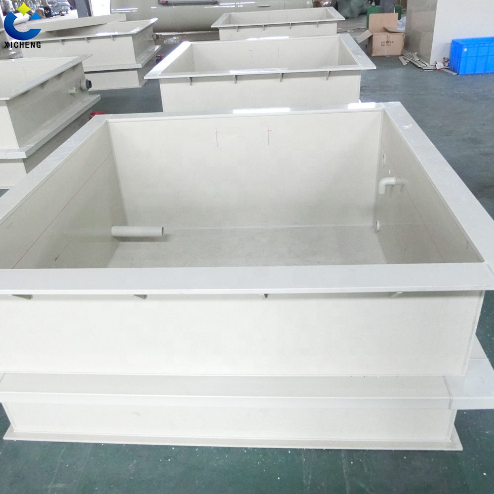
An open top tank is a vertical vessel with no permanent roof. That is the whole of most catalogue descriptions, and it is the least useful part of the definition, because a roof is not only a cover. On a closed vessel the top head ties the rim of the shell to itself all the way round, and that tie is what keeps the top of a thin cylinder circular. Take the head off and the vessel still has to hold its circle, with nothing but the edge of the sheet to do it with.
That single change is the whole design problem. Everything a closed tank gets for free at its top edge — the circularity, the weather protection, the still air above the liquid, the somewhere to mount a level instrument — becomes something an open vessel has to be given deliberately, or has to do without. The rim stops being a finish detail and becomes a structural member. The liquid surface stops being hidden and becomes an interface with the room. The lid, if there is one, stops being part of the vessel and becomes an accessory that hangs on the rim.
This page works through what an open tank costs and where. It starts with the hoop load and shows that its peak is not where most people expect it, then treats the rim in the detail the job deserves, then the free surface and the two ways it changes a process, then the mixer that is usually mounted over the opening, and finally the two manufacturing routes and the order in which an open vessel fails. Shape selection between cylindrical and rectangular is a separate question and is treated elsewhere; so is the cone bottom, which has its own geometry to answer for.
Key Takeaways
- The hoop tension in a vertical tank peaks at the base, not at the rim: T = ρgHR, and at the free surface it is zero. An open top tank does not carry more hoop load than a closed one — it carries the same load with one less ring holding its circle.
- Four worked sizes: a 1.2 m batch pot filled 1 m carries 5.9 kN/m at the base; a 2.4 m tank at 2 m of water carries 23.5 kN/m; the same tank at specific gravity 1.9 carries 44.7 kN/m; a 3.0 m tank at 2.5 m depth and 1.9 specific gravity carries 69.8 kN/m. Specific gravity is a straight multiplier with no discount.
- Divide those figures by the wall thickness and the membrane stress comes out in single-digit megapascals. Liquid pressure is not what sizes the wall of an open top tank; the free edge is.
- A 40 mm lip rolled on a 10 mm wall gives 64 times the ring stiffness of the plain wall. Doubling the entire wall to 20 mm gives 16 times and costs material over the full height. Depth beats thickness.
- ASTM D1998 lists agitation among the forces its scope explicitly does not design for. A mixer mounted on a bridge over an open top tank is a separate load case, not a tank accessory.
- We weld open vessels in polypropylene sheet from 5 mm to 30 mm, test at 1.5 times design head, and warrant the body and welds for 12 months.
What an Open Top Tank Is — and the Job the Lid Was Doing
The engineering definition is one line: a vertical shell, open at the top, closed at the bottom, with or without an agitator mounted over the opening. The commercial definition is looser. An open top tank is sold as a dip tank, a batch tank, a mixing tank, a day tank, a brine tank, an acid neutralisation tank or an open top storage tank, and the name a buyer uses usually tells you more about the duty than the drawing does. Where the acid is stored rather than mixed or neutralised, the questions change, and they are collected in our acid storage tank guide.
None of those names is wrong. They are all describing the same property from different directions: the vessel is entered from above, by a person, by a hose, by a drum, by a rack of parts or by an impeller shaft, and everything about it follows from that access. The reason to sort the vocabulary out first is that the words carry the freeboard, the rim type and the fittings with them. A day tank that is filled from a drum every shift and drained every night is a different vessel from a plating tank that sits at temperature all week with racks going in and out.
The Names You Will Meet on a Purchase Order
A dip tank and a chroming tank are both vessels you lower parts into. The first is written by the process, the second by the trade, and neither says anything about whether the liquid is hot, whether it is agitated or whether the vessel is lined. If you are buying one, the useful questions are what the bath is, what its temperature is and how the rack is handled — not which of the two words is on the specification.
A batch tank and a mixing tank both imply turnover rather than storage: product goes in, is worked, and leaves. The difference is whether the working is done by circulation or by an impeller, which is the section on mixer bridges below. A day tank is a small buffer, sized by consumption rather than by process, and its defining feature is that it is filled often and by hand. An open top storage tank is the opposite case: it is filled rarely and holds for a long time, which makes evaporation and contamination the governing problems rather than access.
Reading the name this way is not pedantry. It is the reason two buyers can ask for an open top tank, receive vessels of the same capacity, and find that one is right and the other is wrong. The specification that matters is not the noun. It is the fill frequency, the contents, the temperature, the head above the liquid, and whether anything heavier than a hose will be hung over the edge.
What a Lid Does on a Closed Vessel
A closed top tank’s head is asked to do three jobs, and buyers only ever think about two of them. The first is to cover: keep rain, dust, insects, airborne contamination and the occasional dropped tool out of the contents. The second is to seal, which is only relevant if there is a pressure or a vacuum to hold, or a vapour to contain. The third is to stiffen, and it is the one that disappears silently on a specification sheet.
The stiffening job is easy to miss because a head does not look like a structural element. But a circular plate attached to the top of a cylinder is extremely stiff in its own plane, and a cylinder whose top is closed by one is not free to become oval at that end. The head closes the ring. It does not matter whether it is flat, dished or conical: the moment it is joined around the full circumference, the top of the shell is held circular by something other than its own wall thickness.
Remove the head and the ring is open. Nothing resists the top edge going oval except the wall itself, which is thin, and a thin strip bent out of its own plane is one of the least stiff shapes in engineering. This is why the top edge of a moulded vessel is never simply cut off. Every one of them has something there — a rolled lip, an inward flange, a thickened band — and the section further down explains what that something is for and how much of it you need.
The One Question This Page Answers, and Three It Hands Off
The question is what an open top costs you, and where. It costs you at the free edge, in circularity; at the liquid surface, in vapour and in what condenses back; and at the mounting point, because everything hung over an opening loads the same rim. Those three penalties are what the sections that follow measure and weigh in engineering terms.
Three related questions are deliberately left out. Whether the vessel should be cylindrical or rectangular is a footprint decision rather than a structural one, and the trade is a wall-flush, low-profile shape against the even flow of a round one. How much clear height a standing vessel needs, including the space above its opening, is in vertical tank headroom. What the flat shape asks of the structure, in stiffener pitch and in base frame, is the rectangular side of that trade. Whether the vessel should be single or double walled belongs to containment, where the outer shell has its own design rules. What those rules have to cover starts with the day the inner shell fails. And how a cone bottom drains belongs to the cone, whose angle and outlet geometry decide everything about it. Each of those has a page of its own because each one changes the answer rather than adding to it.
The overall selection of a vertical plastic tank — resin families, temperature limits, chemical resistance, fittings and service life — sits above all of this. If you have not settled that yet, the resin discussion in our polypropylene tank guide is the better place to start, and the rest of this page will still be here afterwards.
Where the Hoop Load Actually Peaks — and What the Open Top Really Costs
Almost every description of an open top tank says the same thing in different words: without a lid, the load has nowhere to go but the wall. It sounds plausible, it is repeated everywhere, and it is not what happens. Working out where the load actually is takes one line of arithmetic, and the answer changes what you should specify.
Hoop Tension in One Line: T = ρgHR
Cut a filled vertical cylinder in half through its axis. The liquid pushes the two halves apart. The force on one half is the pressure multiplied by the projected area, which for a tank of radius R filled to depth H is the pressure at each level integrated down the wall. The two walls resist that force in tension, one at each cut. Set the two equal and the tension per metre of wall height at the base is T = ρgHR, with ρ the liquid density, g the gravitational acceleration, H the depth of liquid above the point you are asking about, and R the radius.
The H in that expression is not the tank height. It is the depth below the free surface, which is what makes the result interesting. At the bottom of the tank H is at its maximum and so is T. At the top of the tank H is zero, so T is zero, and an open tank is the case where that top edge is all there is. The free surface of a liquid exerts no pressure on the wall at its own level, whether there is a lid above it or not.
So an open vessel does not put more hoop tension into its wall than a closed one holding the same liquid to the same depth. The tension at the base is identical. What the open top changes is the other end — the end where the tension is zero but the vessel still has to stay round, and where previously there was a head doing that and now there is only an edge.
Four Sizes Worked Through
The formula is worth running on real dimensions, because the numbers are smaller than the language around open top tanks suggests. Specific gravity enters directly: a liquid at 1.9 specific gravity has a density of 1,896.6 kg/m³ against 998.21 kg/m³ for water at 20 °C. Gravitational acceleration is taken as 9.81 m/s².
| Duty | Radius R | Liquid depth H | Density ρ | Hoop tension T at base |
|---|---|---|---|---|
| Batch pot, 1.2 m diameter, water | 0.60 m | 1.00 m | 998.21 kg/m³ | 5.88 kN/m |
| General vessel, 2.4 m diameter, water | 1.20 m | 2.00 m | 998.21 kg/m³ | 23.50 kN/m |
| Same vessel, specific gravity 1.9 | 1.20 m | 2.00 m | 1,896.6 kg/m³ | 44.65 kN/m |
| Large vessel, 3.0 m diameter, specific gravity 1.9 | 1.50 m | 2.50 m | 1,896.6 kg/m³ | 69.77 kN/m |
Two things fall out of the table. The first is that specific gravity is a straight multiplier: going from water to 1.9 doubles the tension to within rounding, because nothing else in the expression changed. The second is that diameter and depth both appear once, so on paper they are equivalent levers. In practice they are not, and the next part explains why.
Specific Gravity Is a Straight Multiplier, and Diameter Is Harder on the Rim
Buyers routinely describe a tank by its volume and then discover that the same volume in a dense liquid is a different vessel. Two thousand litres of water weighs two tonnes. Two thousand litres at 1.9 specific gravity weighs 3.8 tonnes, and the hoop tension is 1.9 times as high at every level. Some moulded ranges are published with a working specific gravity limit for exactly this reason, commonly at or below 1.9, and it is a limitation of the wall and the fitting details rather than a comment on the resin.
Diameter and depth are the same as multipliers in the formula, but they are not the same as decisions. Adding depth raises the pressure at the base and leaves the top edge where it was. Adding diameter does that and one more thing: it enlarges the circle that the rim has to hold. The deflection of a ring under a given pair of imposed loads grows roughly with the cube of its radius for a section that does not change. Double the diameter and you have doubled the tension and multiplied the rim’s problem by about eight.
That asymmetry is the useful takeaway. If the vessel is coming out under-strength at the top, the cheapest mistake to avoid is growing the diameter for capacity. Going taller is the kinder change, provided the freeboard and the stand still work. Going wider buys volume at the expense of the part of the vessel that was already marginal.
What the Lid Was Really Doing
The head was not carrying the hoop load. The wall carries it, in tension, and the peak of that tension is at the base where the pressure is highest. What the head was doing was holding the top of the wall to a circle, and this is a different kind of help altogether. Tension along the wall is easy work for a thin membrane. Resistance to a change of cross-sectional shape is not, because it requires bending stiffness in the wall’s own plane, and a sheet’s in-plane bending stiffness is its thickness cubed.
Remove the head and you have introduced a free edge. In shell terms a free edge is where the clean membrane picture stops being true: the shell can no longer carry the load purely as tension, bending appears within a short distance of the edge, and the edge itself can move. On a thin open vessel that movement shows up as ovality — the top edge going slightly elliptical, then more so, with the wall following it down for a hand’s width or two.
Ovality is not a cosmetic defect. Once the cross-section is out of round, the wall’s load path is no longer a pure ring in tension; bending is superimposed on it, and bending is what starts cracks at penetrations and at weld toes. It also breaks the fit of anything that lands on the rim: a cover, a mixer bridge, a lid that no longer sits flat. The rest of the vessel is usually still sound at the point where the top has already gone.
Membrane Stress Is a Few Megapascals, So Pressure Is Not What Sizes the Wall
Divide the tension by the wall thickness and you get the membrane stress. From the table, a 3.0 m vessel at 1.9 specific gravity with a 20 mm wall runs at about 3.5 MPa; the 2.4 m vessel at 2 m of water with a 10 mm wall runs at about 2.35 MPa. These are hand calculations on the assumptions stated above: a thin shell, a uniform thickness, hydrostatic pressure only, no allowance for temperature, creep, forming, impact or the local effects of a penetration.
They are not a design check and must not be used as one. What they do establish is a rank order. The stress a liquid puts into the wall of a vessel of this size is a single-figure number of megapascals, while the stresses that govern thin-wall plastic vessels in practice come from handling, impact, thermal cycling, fitting loads and the concentration of load at edges and openings. The wall is not being sized by the liquid.
The practical consequence follows directly. If the wall is not limited by pressure, then thickening it is not a remedy for a top edge that is deforming, and it is an expensive habit to acquire because it costs material over the whole height. What the top edge needs is depth in its section, at the top, where the ovality happens. The next section is about exactly that.
The Rim: Lip, Inward Flange, or Ring
Every open top tank of any size has a feature at its top edge, and the trade calls it at least three different things depending on how it was made. A moulded vessel has a rolled lip. A vessel formed from sheet may have an inward flange. A fabricated vessel has a stiffener ring welded or bonded on. The words describe the manufacturing route, not the function, and the function is the same in all three cases: put depth into the section at the free edge so the circle stays a circle.
Three Names the Industry Uses for One Part
The rolled lip is what rotational moulding produces naturally. The mould is made that way, the material flows into the form, and the result is a rim with a rounded profile and a wall that turns back on itself. It has no separate part, no joint and no sharp corner, and it is as good as the mould it came out of and no better. You cannot make it deeper afterwards, and you cannot make it continuous past a hole cut for an overflow without doing something else about the interruption.
The inward flange is the same idea turned inwards, and it is used where the top of the vessel is also a mounting face or the start of a cover seat. It gives a flat annular surface for a lid to land on and it puts the stiffening material where the deflection is, but turning the sheet inwards creates a sharper corner on the outside, which is a stress raiser if the corner radius is small. The welded stiffener ring is the fabricated answer: a separate section of the same material, welded around the outside of the top edge, whose size is chosen by the designer rather than by a mould.
Section, Not Area: Why a Formed Lip Beats a Thickened Wall
The property that resists ovality is the second moment of area of the stiffening section about the radial axis, and for a rectangle it goes as the width times the cube of the depth, divided by twelve. Depth is the dimension in the radial direction — how far the stiffening material stands out from the shell. Width is the dimension along the shell. The cube is the whole story.
On a plain 10 mm wall the only material available to resist ovality is the wall itself, so the effective section is 10 mm wide and 10 mm deep. Roll a 40 mm lip on the same wall and the width stays at 10 mm while the depth goes to 40 mm. Compare that with doubling the whole wall to 20 mm, which raises both dimensions together.
| Top edge arrangement | Width b | Radial depth d | Second moment of area | Relative to plain wall |
|---|---|---|---|---|
| 10 mm wall, no lip, edge acting alone | 10 mm | 10 mm | 833 mm⁴ | 1× |
| 40 mm lip rolled on the same 10 mm wall | 10 mm | 40 mm | 53,333 mm⁴ | 64× |
| Whole wall thickened to 20 mm, no lip | 20 mm | 20 mm | 13,333 mm⁴ | 16× |
The comparison is unfavourable to thickening by a factor of four, and it does not account for the material. A lip adds material around one circumference. A thicker wall adds it over the entire height of the vessel. That is why every moulded vessel in a catalogue has a lip, and it is also why a buyer who asks for a heavier wall to fix a floppy rim is buying the wrong thing twice.
The section’s own width matters too, and this is where an inward flange or a fabricated ring can beat a plain lip. A ring section that is 40 mm deep and 30 mm wide has more than three times the second moment of area of a 40 mm lip on a 10 mm wall, for the same depth. Depth is the first lever and width is the second; on a fabricated vessel you can use both.
Where a Rim Stops Being Enough
There is no standard that gives a rim size, and this is worth stating plainly because it is the point at which most buyers stop being able to check a quotation. The storage-tank specifications that exist set out materials, wall thicknesses, tolerances, test methods and the pressure regime, and they stop short of the top edge; a search of ASTM D1998 finds no requirement for stiffening, no freeboard rule and no rim dimension. The rim is a designer’s detail, and it is judged by whether the vessel stays round.
What pushes a rim past its limit is predictable. Diameter is the first, for the reason given in the previous section: the same section resists far less at a larger radius. A cover that has to be carried is the second, because its weight and the wind on it arrive at the rim. A mixer bridge is the third, and it is the worst, because it arrives as a concentrated moment as well as a weight. A tall vessel above a high liquid level is the fourth, since the top band then has more wall to keep in line. And a wide or numerous set of penetrations is the fifth, because every hole interrupts the ring.
Negative pressure is a separate category and worth naming because it is often accidental. An open vessel has no roof to collapse, but the moment a gasketed cover goes on and something draws liquid out faster than air can get in, the vessel is under vacuum and the top has become a flat plate spanning a circle. That is not a condition any storage-tank specification covers; ASTM D1998 states that it does not cover vessels intended for use at pressures other than atmospheric, and a partial vacuum is one of the first things it names when it lists what must be designed separately.
Reading a Rim on a Drawing, and the Four Things to Measure
When a drawing or a sample arrives, four measurements tell you whether the rim is doing its job. The first is the radial depth of the stiffening feature at the top, measured from the outside of the shell. The second is the continuous width of the material in that feature, since a folded lip and a welded ring of the same depth are not the same thing. The third is the corner radius between shell and stiffener; a tight corner concentrates stress exactly where the bending is greatest.
The fourth is continuity. Follow the rim all the way round and see whether anything interrupts it: an overflow notch cut through it, a hand-hole, a bracket welded across it, a lid hinge bolted through it. Any interruption is a break in the ring, and the load that the ring was carrying has to get past that break somehow. A notch in a rim is not a detail. It is a cut in the member.
The straight-edge test is the one to do on site, and it costs nothing. Lay a straight edge across the opening in two directions at right angles and measure the gap between edge and rim. A vessel that was round when it was installed and is not round now has told you something about its loading that no drawing will. Do it before adding a cover or a bridge, because after those two are on, the measurement is no longer a baseline.
Freeboard, Overflow, and the Level You Can Trust
A closed tank has a defined top. Its ullage is a designed volume, and the highest liquid level is set by a nozzle, a float or a level instrument. An open top tank has a spill plane, and the spill plane is the top edge. That sounds like a small difference and it changes three things at once: what the stated capacity means, what happens when a fill does not stop, and where the liquid goes when it does not.
The Spill Plane Is the Rim, Not the Nominal Capacity
Two suppliers can quote the same nominal capacity for the same diameter and come out with vessels of different depth, because “capacity” has no agreed datum. It may mean the volume up to the rim, the volume up to a nominal working level, or the volume below an overflow. An open top tank with no overflow has no datum at all except the rim, and a buyer who assumes the stated volume is usable is assuming that the top of the liquid can be the top of the vessel.
The question to ask is short and it belongs in the enquiry: capacity up to what level, and what freeboard is left above that level. If the answer is that there is no freeboard, the vessel has been sized to the rim, and the first unexpected event at the inlet will put liquid on the floor. Freeboard is not wasted capacity. It is the only buffer an open vessel has.
Freeboard and the Inlet Shock No One Models
The events that overfill an open vessel are ordinary. A fill valve sticks open. A level switch fails in the safe direction it was not tested for. A batch is made up by hand and the operator fills to a mark. A recirculation loop is left running while the draw-off is closed. A liquid expands as it heats. Foam lifts the apparent level well above the true one. None of these needs a fault in the vessel; they need only a process with a person in it.
Freeboard answers all of them at once, which is why the amount of it should be a decision rather than a leftover. A tank that is filled automatically and has a high-level alarm needs less than one filled from a drum by hand. A vessel whose contents foam needs more than the same vessel with a clean liquid, and a vessel that is heated needs allowance for expansion between cold fill and hot running. An overflow connection, taken through the wall below the rim, converts an overfill from a spill into a drain — and it interrupts the rim at exactly the point where the rim is working hardest, so the stiffening has to be maintained around the opening.
There is a second, less obvious inlet effect. A fill line discharging above the liquid surface drops liquid from a height, and the impact stirs the surface, entrains air and in some duties creates a static charge. Submerged filling avoids all three. The higher the freeboard, the further the drop, which is an argument for keeping the fill connection low rather than for keeping the freeboard small.
Open Top Water Tank Duty: Rainwater, Process Water, Town Water
The water duties are where the open top form is most common and where its compromises show most clearly. A rainwater harvesting tank is open because it is filled by a downpipe and drawn from the top; a process water buffer is open because it is filled and drawn continuously; a break tank on a town water supply is open because the air gap between the supply pipe and the water surface is a required safety feature, not a design choice.
In all three the free surface is the problem. An open top water tank collects whatever the air carries, grows biological film in daylight, and loses the volatile fraction of any treatment chemical dosed into it. A cover solves most of that and costs the access that made the form attractive. The usual compromise for an open top water storage tank is a loose cover that can be lifted whole, or a hinged cover over the part of the opening that is used, with the rest closed permanently.
Water supply practice usually imposes its own conditions on these vessels. A potable break tank in most jurisdictions needs a screened vent or an open top with a screen, and the air gap has to be maintained whatever the cover arrangement, because the gap is the backflow protection. That is a plumbing requirement rather than a tank requirement, and it is worth confirming before the vessel is ordered rather than after the cover has been made.
Instrumenting the Level Without a Roof to Mount On
A closed tank gives you a nozzle on the top head, and every level technology mounts to it. An open top tank gives you a rim and nothing above it. The four practical answers are a float switch hung from a bracket that spans or bridges the rim, an ultrasonic or radar head on the same bracket looking down, a sight tube taken from two wall fittings, and load cells under the legs where the vessel is small enough to weigh.
Each has a condition attached. A bracket that spans the rim is a load on the rim, and on a thin-walled vessel it is not a trivial one; it should land over the stiffening feature and be as light as the duty allows. An ultrasonic head looking at a free surface is disturbed by foam, by vapour and by the surface movement an agitator creates. A sight tube is reliable and needs two penetrations at heights that suit the working range. Load cells need the vessel’s pipework to be flexible, or the weight goes down the pipes instead of into the cells.
Whichever is chosen, mount it so that the instrument can be removed without draining the vessel, and so that the bracket does not become the thing that stops the rim being inspected. On an open vessel the top edge is both the mounting point and the component most likely to deform, and the two have to be arranged to coexist.
Evaporation, Condensation, and What Comes Back Down
An open top tank has a free surface, and a free surface is an evaporating surface. That single sentence explains most of what an open vessel does to a process over a week, and it explains the second thing as well, because whatever evaporates has to go somewhere and a lid is where it stops.
The Free Surface Is an Evaporating Surface
The rate at which a liquid leaves a surface depends on the area of that surface, the vapour pressure of the liquid at its temperature, the movement of air across it and the temperature difference between liquid and air. An open vessel offers the full plan area of the vessel to all four at once. A closed tank offers only the small area under a vent, which is why the same contents in a closed plastic chemical storage tank can sit for months with a concentration that barely moves.
What that means in practice depends on what is in the tank. A dilute aqueous solution loses water and concentrates, which shifts every dosing calculation downstream. A bath containing a volatile component loses that component preferentially, so the composition drifts in a direction nobody planned. A hot bath in a room with air movement loses both, and the loss is fastest where the surface is largest, which is precisely where the vessel was made wide for access.
The same mechanism turns the open surface into an emission point. Whatever leaves the liquid enters the room, and that is a ventilation question before it is a tank question. The regulation that governs it is written in terms of exposure limits for the substances concerned, and it sets the order of remedies clearly: to achieve compliance, administrative or engineering controls must first be determined and implemented wherever feasible, and protective equipment is the fallback when they are not. A tank that is open by design has no engineering control built into it. The control has to be extracted at the rim, and the rim is not shaped for it.
What a Lid Returns to the Batch
Put a lid on and the vapour does not disappear. It condenses on the underside, which is the coldest surface it meets, and it runs back into the tank. On a cold vessel full of cold liquid this is harmless. On a hot process bath it is not, because the condensate is nearly pure water returning to a bath whose water content was the thing being controlled.
The result is a drip point. Liquid that has crept across the underside of a lid collects at the lowest spot and falls from there, and it falls in the same place every time. In a plating or pickling bath that place is a defect site: parts passing under it get a locally diluted patch, and the patch is repeating rather than random, which is what makes it hard to diagnose. The mechanism is general, but the tolerances are not, and the ways a bath mitigates it are set out in pickling tank design. The usual fix is a lid with a slope and a drainage path back to the wall rather than to the middle, or a lid designed to shed condensate outside the working area.
The other thing a lid returns is dust, in the sense that it stops returning to the tank. An uncovered surface collects airborne solids continuously, and in a plating bath settled dust is a contaminant that shows up as roughness. The same cover that causes the drip is the cover that keeps the dust out, which is why the answer to the drip is a shaped lid rather than no lid.
Sunlight on the Surface, and the Stratification It Builds
An open vessel in daylight has no roof to shade its contents. A dark liquid absorbs at the surface, the surface layer warms, and because plastic is a poor conductor and liquids mix poorly without help, the warmth stays where it is. The result is a stratified vessel: a warm layer at the top, cooler below, and a density difference that resists mixing. An agitator drawing from the bottom then pulls cool liquid and returns it to a warm surface, and the temperature the process sees is not the temperature the instrument reads.
Sunlight does two more things that matter over a service life. It raises the surface temperature of the liquid and of the upper wall, which is the part of the vessel already carrying the least pressure and the most handling. And it drives the biological growth that turns an open water tank green, which is a maintenance burden that a cover removes entirely, at the expense of access that is used less often than the buyer expected.
When a Cover Earns Back the Access You Give Up
There are three cover arrangements and they are not interchangeable. A loose cover sits over the opening and is lifted off whole; it is the cheapest, it is the easiest to use and it protects nothing against a fall or a wind. A hinged cover stays attached at one edge and can be propped or left open; its hinge, and whatever holds it open, are loads and fixings on the rim. A bolted and gasketed cover seals, which makes the vessel a closed tank in the only sense that matters structurally, and it carries the warning about vacuum that applies to every closed vessel.
| Cover arrangement | Keeps out | Load added to the rim | What it changes about the vessel |
|---|---|---|---|
| None | Nothing | None | Free surface and vapour open to the room |
| Loose, lifted whole | Rain, dust, debris | Its own weight, distributed, while seated | Nothing structurally, if the rim is continuous |
| Hinged, left open in use | Rain, dust | Hinge reaction and a cantilevered moment when open | Adds a concentrated moment at one point on the rim |
| Bolted and gasketed | Everything, including vapour | Sealing compression around the full circumference | Vessel is sealed: no vacuum, no pressure, and venting becomes mandatory |
The decision follows from how often the opening is actually used. If it is used every shift, a loose cover will be left off and a hinged one will be left open, and both are protecting nobody. If it is used once a week, either works and the loose cover is the better bargain. The moment the cover has to seal, the vessel has left the territory of open top tanks, and its vent, its relief and its design pressure all need an answer.
The Mixer Bridge: A Second Load on the Rim
Most open top tanks of any size have an agitator over them, and the bracket that holds it is where a great many of them go wrong. The reason is simple: the opening is at the top, so the mixer has to be supported from the top, and the only things at the top are the rim and a bridge across it. Whatever those two were designed for, it was not a rotating machine.
Where the Bridge Lands, and Why Never on the Shell
A mixer bridge is a beam or a frame that spans the opening and carries the drive, the shaft and the impeller. Its supports land at two points at least, and those points are either on the rim or on an independent structure. They should not be on the shell below the rim, and the reason is about how a thin wall carries load rather than about thickness.
A thin cylindrical wall is efficient in tension. The hoop tension from the liquid is exactly the kind of load it handles well, and the numbers in the earlier table show how comfortably. It is poor in bending, especially local bending at a point where something is bolted through it. A mixer mount on the shell creates a concentrated moment, a ring of bolt holes, and a stress concentration in a membrane that has no spare capacity for bending. The wall does not simply take the load; it distorts locally, and a distortion at a bolted pad becomes a crack at the edge of the pad.
Landing the bridge on the rim is better because the rim is already the stiffest thing at the top, and because a load applied to the rim travels down the wall as membrane force rather than as local bending. The rim is also already doing the circularity job, so a modest increase in its section serves both purposes. What the rim is not good at is a concentrated moment from a single point, which is what a hinged cover or a cantilevered bridge produces.
ASTM D1998 Lists Agitation Among the Forces It Does Not Design For
The standards situation is unusually clear and almost never quoted. The polyethylene upright storage tank specification defines what it covers, and then states that special design considerations that are not covered in the specification shall be given to vessels subject to superimposed mechanical forces, such as seismic forces, wind load or agitation; to vessels subject to service above the specified temperature; and to vessels subject to specified superimposed water pressure. Its scope paragraph repeats the point from the other direction, naming externally imposed mechanical forces, internal pressure or vacuum and higher temperature service as conditions beyond its scope for which other sources of standards shall be consulted.
Agitation is listed by name. That is not a technicality: it means a mixer mounted over an open vessel is not covered by the tank specification, and the mount, the bridge and the local reinforcement have to be justified as their own load case. It also means that a supplier who sells a tank and a mixer as a package has taken on a design question that neither the tank standard nor the mixer standard answers on its own.
The Standalone Agitator Support, and When It Is the Better Answer
The alternative to a bridge is a frame that stands on the floor and carries the mixer independently, with the shaft passing through the opening without touching it. The tank then carries no mixer load at all: no bridge, no bracket, no rim moment. The frame needs its own foundation or its own feet, and it needs to be positioned so that the shaft runs concentrically within the clearance available.
Independent support is usually the better answer in four situations. When the vessel is large, because the rim moment scales with span. When the mixer is heavy or has a large overhung shaft, because the dynamic load is the part nobody calculates. When the vessel is thin-walled or the rim is a simple rolled lip with no capacity to spare. And when the duty will run continuously, because vibration that is tolerable for a week is not tolerable for a year, and a frame is much better at absorbing it than a welded bracket on a plastic wall.
It costs floor area and it complicates the layout. Where the vessel is small, the mixer is light and the duty is intermittent, a bridge over the rim is the sensible engineering and works for years. The mistake is not choosing the bridge. It is choosing it without noticing that a choice was made.
Vortex, Off-Centre Mounting, and Baffles in an Open Vessel
An open vessel has a free surface, and a free surface is free to rotate. A centrally mounted impeller in an unbaffled tank will develop a vortex at a lower speed than the same impeller in a baffled tank, and the vortex deepens as the speed rises until it draws air down the shaft. Air entrainment then shows up as foam, as loss of pumping capacity and, in a duty where the air reacts, as a chemical problem.
There are three standard answers and each has a penalty at the rim. Baffles welded to the wall resist the rotation and are the most effective, but they are wall attachments carrying a fluctuating load and they interrupt cleaning. Baffles hung from a bridge are common on open tanks for exactly that reason, and they put an out-of-plane load into the bridge rather than into the wall. Off-centre mounting breaks the symmetry and suppresses the vortex without any baffle at all, and it is the simplest of the three to build, at the expense of an eccentric load on the bridge and a shaft that is no longer vertical in the drawing.
Whichever is used, the decisive number is the shaft’s overhung length and its critical speed, which belongs to the mixer supplier and not to the tank supplier. What belongs to the tank is the stiffness of whatever the drive is bolted to. A flexible bridge on a flexible rim will shift the shaft’s critical speed downwards, and a duty that was fine on paper will run through a resonance at a speed the process actually uses.
Two Ways to Build an Open Top Tank
Open top plastic tanks reach the same shape by two manufacturing routes, and the route decides what the rim can be, what the diameter can be and which materials are available. Buyers are rarely told which route a quotation is on, and it is the single most useful question to ask about an open top plastic tank.
Rotomolded One-Piece: Seamless, but the Rim Is Whatever the Mold Gave You
Rotational moulding produces a vessel with no seams, no welds and no joints, in a single piece from a single charge of resin. The interior is smooth and continuous, which is what makes the route attractive for food contact and for duties where any crevice is a cleaning problem. Wall thickness is controlled by the charge and the mould’s thermal behaviour, so it varies somewhat from point to point rather than being uniform, and it is thicker at corners where the material pools.
The constraint is the mould. The diameter, the height, the rim profile and the position of every fitting are fixed by tooling, and a change to any of them means a new tool or a modification. That is why lids for these vessels are sold a size at a time rather than made to order, and why the rim is a profile rather than a dimension: you get the lip the mould was cut with. Rotomolded ranges also carry a published working specific gravity, commonly at or below 1.9, which is a statement about the whole vessel rather than about the resin.
Welded Polypropylene Sheet: Any Diameter, but the Rim Becomes a Weldment
A fabricated vessel is built from sheet, formed and welded, and its dimensions are limited by handling and transport rather than by a mould. That freedom is what makes the route useful at the large end, and it comes with obligations. The top edge is no longer a rolled profile; it is a joint. The stiffening has to be designed, made and welded, whether as a ring of the same sheet welded around the outside of the top, as an angle section, or as a thickened band formed by folding the top of the wall over.
The rim is one of the decisions that route forces, and the rest of them are set out in how a fabricated vessel is built from sheet.
That puts the rim weld in a difficult position, because the rim is the part of the vessel that takes the handling: the hose dragged over it, the rack rested on it, the drum set down on it, the cover dropped onto it. A weld at a free edge is also where bending concentrates. In our own fabrication the sheet runs from 5 mm to 30 mm, welds in thick sections are inspected ultrasonically, and the finished vessel is tested hydrostatically at 1.5 times design head, which is a test of the body and the joints rather than of the rim.
The practical difference for a buyer is that a fabricated open top plastic tank can be given a rim the duty justifies, and can be given it continuously around a penetration instead of having the penetration cut through it. It can also be given a rim that is a proper section rather than a folded edge, which is where the width term in the second moment of area comes from. The two duties that most often come through this route are covered on our PP chemical storage tanks and PP pickling and electroplating tanks pages.
Resin Choice Is Only Half the Answer
The resins that appear in open top plastic tanks are polyethylene, cross-linked polyethylene and polypropylene. Polyethylene is the default for moulded vessels and for water duty, cross-linked polyethylene is used where environmental stress cracking resistance matters more than weldability — and it cannot be welded, so it is unavailable to the fabricated route — and polypropylene is the choice for chemical duty and for higher service temperatures, and it welds readily.
Food and potable water claims need care, because the regulation is more specific than the label. The food-contact regulation for olefin polymers identifies polyethylene for food-contact articles within a density range of 0.85 to 1.00 g/cm³ and polypropylene within 0.880 to 0.913 g/cm³, with a melting range of 160 to 180 °C for the polypropylene entry. It then splits polyethylene by use, giving articles that hold food during cooking a different maximum extractable fraction from articles that do not, at the same density.
Two things follow. A resin’s compliance is not the same statement as a finished vessel’s compliance, because colourants, stabilisers and processing all belong to the article rather than to the polymer. And the use category is part of the compliance, so a vessel qualified for storing a food is not automatically qualified for holding it during cooking. For drinking water duty a separate certification regime applies to the finished component, and it is normally evidenced by a certificate rather than by a resin datasheet.
The Failure Order to Inspect, Top Down
Open vessels fail in a fairly consistent order, and the order starts at the top, which the previous sections have been building towards. Checking in that order on a plant walk-round finds the problem while it is still a measurement rather than a repair.
First, ovality at the rim. Measure across the opening in two directions at right angles, compare with the as-installed figure, and look along the rim for a wave. Second, the top band of the wall below the rim, where a bulge or a polished band marks the point where the wall is being bent rather than stretched. Third, the penetrations in and just below the rim: overflow, hand-hole, bracket and hinge fixings, where a crack begins at the edge of the hole and runs with the bending. Fourth, the rim weld on a fabricated vessel, particularly on the outside where the toe of the weld meets the sheet.
Two materials tell you the story before a crack does. Polypropylene shows stress whitening as a pale band before it fails, and it is visible in ordinary light. Polyethylene in a sunny position shows chalking and colour change on the surface facing the weather, which is a signal about ultraviolet exposure rather than about load. Neither is a defect on its own. Both are the earliest evidence you will get.
What you will not find by looking is the reason. An oval rim on a vessel that has been in service for years is usually a lid that was hung on one side, or a bracket that was added, or a bridge that was bolted on later. The rim did not fail; it was loaded. Which is why the first thing to record is what has been added since the vessel was installed.
Frequently Asked Questions
What is the difference between an open top tank and a closed top tank?
The obvious difference is the roof and the obvious consequences are contamination, evaporation and access. The difference that matters structurally is that a closed tank’s head holds the top of the shell to a circle, and an open tank’s rim has to do that on its own. That is why every open top tank has a stiffening feature at its edge and why the hoop load itself is not higher without a lid.
How thick should the wall of an open top tank be?
Thicker than the liquid pressure alone would require, and the pressure is not what decides it. A worked example on this page puts the membrane stress at a few megapascals in vessels of ordinary size, well below what the material can carry, while handling, impact, thermal cycling and fitting loads are all higher. The number to ask for is the sheet thickness with the forming allowance stated, and the design stress at your service temperature from the sheet supplier.
Can an open top tank hold a liquid heavier than water?
Yes, and the hoop tension rises in direct proportion: at 1.9 specific gravity it is 1.9 times the water figure at the same diameter and depth. What changes is not only the wall but the whole support path — the base, the legs, the floor — and the rim, because a heavier duty usually comes with a larger vessel. Several moulded ranges publish a working specific gravity limit, commonly at or below 1.9, and it should be treated as a limit of the vessel rather than a recommendation.
What stops an open top tank overflowing?
Nothing built into the vessel. The spill plane is the rim, so freeboard above the working level and an overflow connection below the rim are the two provisions that exist, and both have to be specified. The overfill events are ordinary rather than exotic: a stuck fill valve, a failed level switch, a manual fill to a mark, a draw-off left closed. Size the freeboard for the worst of them and take the overflow through the wall rather than over the top, maintaining the rim stiffening around the opening.
Should an open top tank be cylindrical or rectangular?
Rectangular if the space decides the vessel: a fixed footprint, a wall to sit against, a bench or a vehicle to fit, several vessels in a row with no gaps. Cylindrical if the contents decide it: an agitator needing an even flow pattern with no corners to collect material, and a full drain-down. The structural question on this page applies to both, because both have a free edge at the top.
Can a lid be fitted to an open top tank?
Yes, in three arrangements that are not interchangeable. A loose cover lifts off whole and adds only its own weight. A hinged cover adds a concentrated moment at its hinge. A bolted and gasketed cover seals the vessel, at which point it is a closed tank: it needs a vent, it must never be drawn under vacuum, and the tank specification it was bought against explicitly does not cover those conditions.
Get an Open Top Tank Built to Your Duty
Three inputs settle most of an open vessel. The first is the duty, meaning what the contents are, their specific gravity, their temperature and whether they settle, foam or evaporate. The second is the top opening, meaning its clear diameter, what has to pass through it and whether anything will be mounted over it. The third is the height above the liquid, because freeboard and access pull in opposite directions and one of them has to be chosen.
With those three we can size the rim, place the fill and the overflow, allow for a cover or a bridge if one is coming, and draw the vessel against a number rather than a habit. Send us the duty, the specific gravity and the top opening and we will come back with a drawing and the rim section that goes with it.
We have been fabricating industrial plastic equipment since 2009, which is 17 years. Our vessels use 5 mm to 30 mm polypropylene sheet, hydrostatic testing at 1.5 times design head, ultrasonic inspection of thick-section welds and a working tolerance of ±2 mm. We operate more than 40 production bases and offices, and hold ISO 9001, ISO 14001, CE, SGS and RoHS.
Note on the figures — The hoop tensions, membrane stresses and second moments of area on this page are our own hand calculations from the formulae shown, on the dimensions stated in each table, and can be checked by any reader: T = ρgHR with g taken as 9.81 m/s², σ = T/t for the wall, I = bd³/12 for the rim section. They are order-of-magnitude illustrations of where the load goes, not design checks, and they carry no allowance for temperature, creep, forming, impact or the local effects of penetrations. No published standard gives a rim dimension, a stiffening requirement or a freeboard rule for an open top tank; ASTM D1998 is cited for the scope its own abstract states and for its explicit list of loads it does not design for, and it is not a certificate for a welded vessel of this kind. Resin density and melting data are specification values for the polymer, not service limits for a finished article. Water density is a physical constant at 20 °C as published. Wall thickness, test pressure, tolerance and warranty are our manufacturing figures.
Sources
- ASTM International — ASTM D1998-21, Standard Specification for Polyethylene Upright Storage Tanks (scope limited to flat-bottom, upright, cylindrical tanks moulded in one-piece seamless construction by rotational moulding, for above-ground vertical installation at atmospheric pressure, capacities from 1,900 L upward; explicit statement that the specification does not cover vessels intended for pressures other than atmospheric, does not cover portable tanks, and is not for vessels used with liquids heated above their flash points in continuous service; special design considerations required, and expressly not covered, for vessels subject to superimposed mechanical forces such as seismic forces, wind load or agitation, for service above specified temperature, and for superimposed water pressure, with other relevant sources of standards to be consulted).
- U.S. Electronic Code of Federal Regulations — 21 CFR 177.1520 — Olefin polymers (polyethylene for food-contact articles in the density range 0.85–1.00 g/cm³, with a separate entry and a different maximum extractable fraction for articles used for packing or holding food during cooking; polypropylene in the density range 0.880–0.913 g/cm³ with a melting range of 160–180 °C, and 150–180 °C for the propylene homopolymer entry).
- U.S. Electronic Code of Federal Regulations — 29 CFR 1910.1000 — Air contaminants (paragraph (e): to achieve compliance with the section, administrative or engineering controls must first be determined and implemented whenever feasible; where such controls are not feasible, protective equipment or other protective measures are to be used to keep employee exposure within the limits prescribed; Table Z-1 sets the limits themselves).
- The Engineering ToolBox — Water — Density, Specific Weight and Thermal Expansion Coefficients (at 20 °C: 998.21 kg/m³, 8.3304 lb per US gallon).