
Electric Air Valve: One Name, Two Machines
Search for an “electric air valve” and you will find two different products under the same name. On the one hand there is the air solenoid valve, a compact coil-and-plunger device that snaps a small air line open or closed in milliseconds. On the other hand there is the motorized electric air valve, a powered damper in a duct that rotates a blade smoothly and holds any intermediate position. On the supply and fresh-air side of that same duct network, the powered damper’s outdoor-air intake, zone-branch, and economizer duties are covered in the electric motorized damper guide. Shoppers come looking for one and are often handed the other, which is how a plastic fume line ends up with a solenoid that cannot regulate, or a pneumatic air system is burdened with a slow motorized valve that only ever needed to switch.
This guide separates the two machines, explains how each electric air valve works, and then focuses on the industrial motorized electric air valve that regulates airflow in ductwork and exhaust systems. The exhaust-specific edition of that machine, with code-mandated shutoff, fail positions, and the corrosive streams it must survive, is the electric exhaust valve guide. It covers construction, control signals, sizing, fail-safety, and the corrosion-resistant plastics that make the valve usable on acid fume lines. The wider electric valve guide covers the whole automated family, from solenoid to globe; here the medium is air and every trade-off follows from that one fact. Because air is compressible and flows at low pressure through large ducts, the electric air valve turns out to behave more like a motorized damper than like a liquid control valve, and the whole article is built on that difference.
What Is an Electric Air Valve?
Two Families Behind One Name
“Electric air valve” is a working term, not a catalog category, and the same words describe two different mechanisms. The first is the solenoid air valve: a magnetic coil pulls or releases a plunger that opens or blocks a small orifice, giving fast two-position service on compressed-air lines, pneumatic pilots, and latching circuits. The second is the motorized electric air valve: a small motor and gear train rotate a damper blade in a duct through 90 degrees, and the control board can stop that blade anywhere between closed and open. Both are electrically controlled valve types, but they answer different questions: one asks whether air should flow, the other asks how much air should flow.
The confusion is costly in practice. A procurement list that says “electric air valve” and nothing else can bring back a 12-volt solenoid when the process actually needs a modulating damper that tracks a 4-20 mA signal. The industrial motorized electric air valve described here is the duct-side instrument: it replaces a manual damper or a balancing louver with a motorized blade that responds to a controller, and it is the product this manufacturer builds in engineering plastics.
Anatomy of an Industrial Electric Air Valve
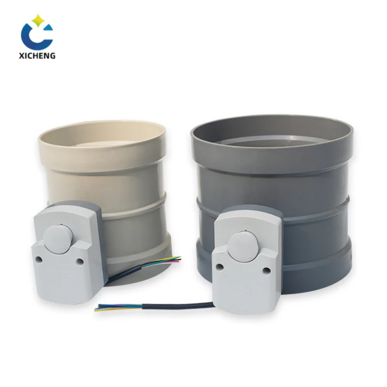
The motorized electric air valve is assembled from two halves. The valve body is a short section of duct, usually round from about DN50 up through DN315 and beyond, with a circular blade pivoting across the bore on a central shaft. The second half is the electric actuator: a motor, a reduction gear train, a control board, end switches, and usually a manual handwheel. When the motor turns, the gears reduce its speed and multiply its torque, and the shaft rotates the blade from parallel with the flow, which is fully open, to across the flow, which is closed.
The drive train in detail is the territory of the electric valve actuator guide, which explains motor, gearing, duty, and torque sizing for every valve body. What matters here is that the blade is the same quarter-turn element that the plastic duct damper guide covers in its manual form, simply fitted with a powered head. On the manual side an operator turns a handle and the blade stays wherever it is left; on the electric side the actuator drives the blade and locks it mechanically at the commanded angle.
The Duct-Side Control Element
In instrumentation language a control valve is the final control element that throttles a fluid at the command of a controller. On a liquid or steam line that element is a ball, globe, or butterfly body. On an air duct the same job is done by a damper: a blade, louver, or butterfly that the instrumentation textbook classes under dampers and louvres, the air-side relatives of control valves. An electric air valve is therefore the powered damper that converts a throttling element into an automatically positioned one.
Damper Blade vs. Pipe Valve
The duty differences matter more than the label. An air damper operates at low pressure, often a few hundred pascals of static pressure rather than the megapascals a pipe valve sees, so the blade and shaft carry small forces and the actuator torque demand stays modest. The flow is also compressible, so pressure drop across the blade converts into velocity rather than a heavy head of liquid. Ducts are large in diameter too, which is why the air-side control element is favoured from DN80 upward where a pipe valve of the same capacity would be bulky. The mechanics of the dampers used in air-handling and combustion systems, and how a blade throttles flow, are developed in the damper reference.
Solenoid Air Valve vs. Electric (Motorized) Air Valve
The most useful distinction in this subject is the one between the two machines behind the name. A solenoid air valve and a motorized electric air valve both run on electricity, and they share almost nothing else. The table below sets them side by side so an engineer can tell which one the application actually needs before a purchase order is cut.
| Factor | Solenoid air valve | Electric (motorized) air valve |
|---|---|---|
| Drive | Electromagnetic coil pulling a plunger | Electric motor through a reduction gear train |
| Position | Two positions only: open or closed | Any intermediate blade angle |
| Response | Milliseconds, a slam-open action | Seconds to about a minute per stroke, smooth |
| Size range | Small tubing, typically up to roughly DN15-DN110 | Duct sizes from about DN50 upward with no practical ceiling |
| Pressure | Direct types need no differential; pilot types use line pressure | Low to moderate static pressure, torque limited |
| Holding | Coil stays energized to hold the position | Mechanical self-lock holds with zero power |
| Typical duty | Safety interlocks, pneumatic pilots, fast shutdown | VAV balancing, scrubber airflow, BMS-modulated dampers |
The Solenoid Air Valve at a Glance
A solenoid air valve uses an electromagnetic coil around a plunger. Current through the coil creates a magnetic field that draws the iron plunger against a spring, and the plunger movement opens or blocks the port. The valve is ordered normally closed, opening when energized, or normally open, closing when energized. The working element moves in a millisecond, which is why the solenoid air valve is the standard fast on/off device for compressed-air sequencing.
Solenoid valves divide into direct-acting and pilot-operated designs. A direct-acting valve lifts the orifice directly with coil force; it has no minimum pressure and suits small flows. A pilot-operated valve uses the process pressure itself, opening a small pilot orifice that relieves pressure above a diaphragm and lets line pressure lift it; it needs a minimum differential of about 0.5 bar, handles larger flows with a smaller coil, and must stay energized to remain open. Port counts complete the picture: two-way solenoids start or stop a line, three-way valves route or mix in pneumatic circuits, and four-way valves shift the two ports of a double-acting cylinder. The mechanics are developed further in the solenoid valve reference, and the solenoid valve product range covers the direct-acting forms.
When a Solenoid Air Valve Wins
Keep the solenoid where the process is fundamentally open or closed. Safety interlocks, emergency air shutoff, pneumatic actuator pilots, purge lines, and the small diverting circuits that sequence machines are all real solenoid work. Nobody wants a half-minute motorized stroke for an emergency stop, and nothing else fits a quarter-inch air tube. On those duties the solenoid air valve is faster, simpler, cheaper, and entirely correct.
When the Motorized Electric Air Valve Wins
The motorized electric air valve takes over the moment the demand is regulation rather than switching. Ventilation that must track fan speed, a fume hood that must hold a constant face velocity as an operator moves, a scrubber that must share air between beds, a cleanroom that must shift airflow between zones: every one of these is a continuous-balancing job that a two-position solenoid cannot perform. The powered damper also holds its position with the motor and gears locked, drawing power only while it is actually moving. Where a duct take-off only needs to be set once without a powered head at all, the manual air valve guide covers the unpowered counterpart.
Electric vs. Pneumatic Air Control
The powered damper itself can be driven in two ways, and the choice decides the whole support system around it. An electric air valve and a pneumatic air valve both rotate the same blade through 90 degrees; the difference is where the energy comes from and what happens when it disappears. The comparison matters most on duct and fume plants, where the electric air valve is usually the better fit.
Pneumatic Air Control at a Glance
A pneumatic air valve is a damper with a pneumatic actuator: compressed air enters the actuator and rotates the blade through the quarter turn, so full pressure parks the blade at one extreme and a positioner holds it anywhere between. The system needs a compressor, air tubing, filter pressure regulators, and usually a solenoid pilot plus an I/P converter to translate a 4-20 mA electrical command into air pressure. The pneumatic strengths are speed, with a stroke in about half a second to a second, and the spring-return actuator, which parks the blade in a defined fail position when air or power is lost, with service lives reported into the million-cycle range.
Why Electric Wins on Duct and Fume Plants
An electric air valve asks for nothing but a power cable and a signal pair. It draws no supply gas, exhausts nothing at the valve, creates no compressor noise or oil mist, and automates directly from the 0-10 V, 4-20 mA, or fieldbus signal a controller already generates, where a pneumatic valve needs converters and a positioner in between. The running-cost story is the compressor: an air system runs continuously to hold pressure, leaking energy through fittings and tubing, while the electric drive draws current only while moving. On fume duty there is a second decisive point: the corrosive air streams that make a duct plant hostile are exactly the streams a compressor and its air lines must survive, so removing the air network removes a maintenance burden.
Because the medium at the valve is low-pressure air or gas, an electric motor and gearbox easily supply the modest torque, without the cramping that large liquid control valves suffer. The electric valves range carries the motorized air and gas dampers of this family, and the electric valve actuator guide expands the drive comparison for every quarter-turn and multi-turn body. The electric control valve for air duty, in other words, is the practical default on exhaust and ventilation systems that have no instrument-air network and do not want one.
Fail Behaviour and Speed
Control character and fail behaviour are where the two diverge most sharply. On loss of power a standard electric air valve holds its last position because the gear train self-locks; a pneumatic spring return parks the blade at the fail position without extra hardware. Speed runs the opposite direction, with pneumatic fractions of a second and electric seconds to about a minute, which is precisely why electric is favoured on high-airflow ducts where an abrupt slam would spike pressure in the system. When a defined fail position is mandatory, electric actuators add a spring or stored-energy return as an option; the powered disc on the pipe side is treated in the electric butterfly valve guide.
| Factor | Electric air valve | Pneumatic air valve |
|---|---|---|
| Drive energy | Power cable only; draws while moving | Compressor, tubing, filter regulators |
| Signal path | Direct 0-10 V, 4-20 mA, Modbus, Profibus | 4-20 mA via I/P converter and positioner |
| Stroke speed | Seconds to about a minute, adjustable | About 0.5-1 second |
| Position on loss | Self-locking gears hold last position | Spring return parks at the fail position |
| Emissions | None at the valve | Compressor energy and purge air |
| Infrastructure | Cable tray and terminal | Compressor room and air piping |
| Enclosure | IP/NEMA rated, explosion-proof options | Explosion-proof, but pilot solenoids need care |
How a Modulating Electric Air Valve Works
Control of air in a duct is regulation, and regulation demands a closed loop. A sensor reads the process value, whether static pressure in the duct, face velocity at a hood, or flow through a scrubber bed, and sends it to a controller. The controller compares the reading with the setpoint and issues a correction to the electric air valve, which moves its blade the required amount. The loop makes the damper a continuously positioned instrument rather than a switch.
Control Signals in Practice
Industrial systems standardise on a 4-20 mA current loop. In the conventional mapping, 4 mA commands the fully closed position, 20 mA commands fully open, and 12 mA stops at the middle at 50 percent; intermediate currents pick every angle in between, so 8 mA sits at one-quarter open and 16 mA at three-quarters. The control board reads the current, drives the motor, and stops when the position feedback matches the request. The blade of an electric air valve is the throttling element, so the board accepts the same 0-10 V signal found on building automation systems, with the voltage acting as a direct position command.
The Hold-in-Place Position Lock
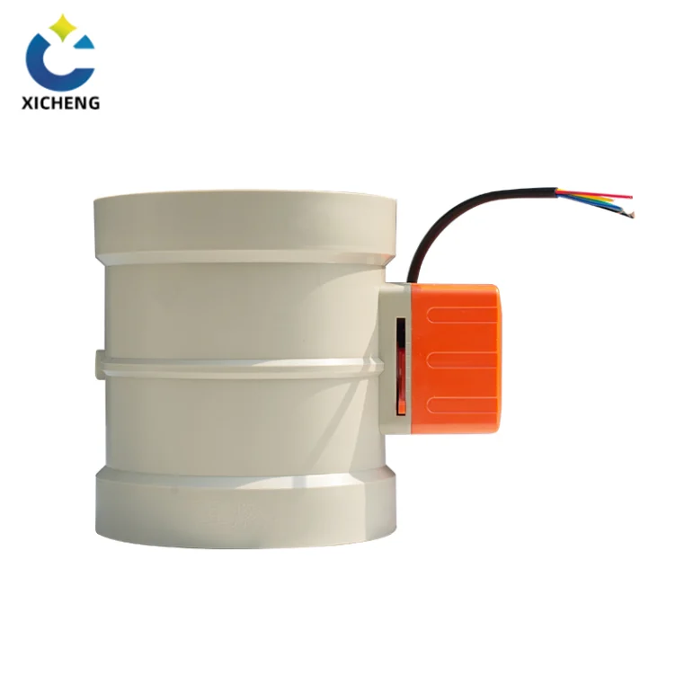
The mechanical signature of a motorized electric air valve is that holding costs nothing. The motor drives the blade through a reduction gear train whose gearing self-locks, so once the commanded angle is reached the motor stops and the blade stays exactly where the loop wants it, with no current drawn. Energy is consumed only during the stroke, typically a slow, controlled 30 to 90 seconds for the full quarter turn on large duct dampers, a far lighter duty than a solenoid that must stay energized to hold, or a spring-return pneumatic that fights air pressure for its whole service life.
Modulation quality depends on position feedback. An encoder or position sensor on the drive reports the actual blade angle back to the board, and the board compares it with the command. On a throttling damper the relationship between blade angle and airflow is far from linear: a few degrees near closed cause large flow changes, and the curve flattens near wide open. The control loop and a correctly sized valve together keep the damper working inside the usable part of that travel.
Control Signals and BMS Integration
An electric air valve earns its place when it can answer the building or process controller, so the electrical interface deserves as much attention as the drive. Three signal families cover nearly every plant: analog current, analog voltage, and digital communication.
Matching the Signal to the Plant
A 4-20 mA loop is the workhorse of industrial control because current is immune to voltage drop over long cable runs, and because a broken wire reads as 0 mA and is recognised as a fault. A 0-10 V signal is common in HVAC and building automation, but the buyer must confirm whether the actuator expects 0-10 V or the offset 2-10 V range, because controller and actuator must share the same calibration or the damper will never reach a true closed or open. Intelligent actuators add digital fieldbus communication such as Modbus RTU or Profibus, which carries position, torque, alarm, and operating-history data back to the control system instead of a single position value. The general architecture of a control valve and its loop is covered in the control valve reference.
On a building or factory automation network, the modulation inputs translate the 0-10 V or 4-20 mA demand into fine blade tracking, giving the control room a live readout of every damper on the duct network. Interlocks and schedules from the BMS then adjust the damper automatically, so a wet scrubber’s airflow, an exhaust hood behind a moving operator, or a cleanroom that shifts air between zones all become closed-loop services rather than fixed manual settings.
Local Controls and Manual Override
Behind the automation, every electric air valve should carry a local face. A handwheel lets a technician move the blade when power is off, and local open-stop-close buttons plus a local-remote selector let field staff take the damper away from the controller during commissioning and maintenance. The manual valve actuator guide describes the unpowered drive head that does this job alone when no electricity is wanted. On a modulating damper, a local position indicator helps the technician compare the blade with the command signal, the same check a commissioning engineer performs at 25, 50, and 75 percent travel.
Sizing and Selecting an Electric Air Valve
Sizing an electric air valve looks different from sizing a pipe valve for one reason: the fluid is compressible. The steps below keep the choice honest on both the airflow and the actuator that must move the blade against whatever pressure is present.
Why Air Sizing Is Different
Air and gas sizing begins with the flow the duct must carry, minimum, normal, and maximum, plus the static pressure in the duct and the pressure drop the damper may add when it throttles. The flow coefficient, Cv or Kv, still measures capacity, but for gas service the calculation must also account for compressibility and pressure ratio, because a given damper passes a different mass of gas at high pressure than at low. Oversizing is the classic failure: a blade chosen purely to match the duct diameter operates almost closed at the normal flow, which puts the loop in the steep part of the curve where small movements create large flow changes, the motor cycles constantly, and the loop hunts. The correct valve should pass the normal flow while seated at a useful intermediate angle, leaving travel in both directions for the controller.
Air ducts differ from liquid lines in one welcome way: the differential pressure across the blade is usually modest, measured in pascals or low kilopascals of fan static pressure, so the torque the actuator needs to overcome fluid forces stays small. The blade area, the shaft seal friction, and the locked-in position each add their share, and a design margin on top of the calculated torque is the standard precaution. Because the medium is compressible, pressure drop across a throttled damper converts into velocity, and a duct throttled too hard can push velocity past the point where the airflow becomes noisy or unstable.
The Five Checks Before You Specify
Run the selection down the same five checks every valve spec sheet demands.
Media compatibility. The air is rarely clean air. Fume exhausts carry acid vapour, solvent, or particulates, so the body, blade, shaft, and seals must resist the stream; on fume lines that means the engineering plastics covered in the next section rather than painted steel.
Control function. State plainly whether the damper must isolate or modulate. An on/off isolation damper only needs end switches and a two-position head; a regulating damper needs a modulating actuator, position feedback, and the duty rating to make many small movements a day.
Flow, pressure, and temperature. Record minimum, normal, and maximum airflow, the duct static pressure, and the working temperature, and derive the Cv or Kv from those numbers rather than from the duct diameter.
Electrical supply. Confirm the available voltage, 24 V DC being common on PLC and BMS systems and 110/220 V AC on standalone plants, so the actuator model matches the site feed, together with the control signal and feedback requirement.
Fail action. Decide what the blade must do on loss of power: hold in place with the standard self-locking actuator, or travel to open or closed when the process or fire-safety logic demands it, using a spring or stored-energy return.
Where the throttled fluid is fuel gas rather than air, the same rule that governs liquid lines holds: a positive shutoff must sit upstream of any modulating damper. The manual gas valve guide explains where that positive shutoff belongs.
Materials for Corrosive Air Duty: PP, PVC, and PPS
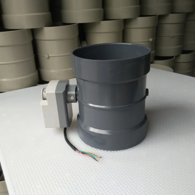
On an exhaust system the electric air valve lives inside the corrosive stream it is trying to move, so the body material is a selection decision, not an afterthought. This manufacturer moulds the valve body as a one-piece injection casting in three engineering plastics, each aimed at a different service envelope.
PP, PVC, and PPS at a Glance
Polypropylene (PP) is the everyday workhorse of wet scrubber and plating-fume ducting. It resists a wide range of acids and alkalis, welds and forms readily, and carries the lowest installed cost, which makes the PP electric air valve the standard choice for acid ventilation networks where cost per diameter is the governing figure. PVC takes over where mechanical rigidity and structural strength matter as much as chemistry: the stiffer material holds its geometry under the loads of a duct run and offers strong inertness to aggressive plating fumes, suiting it for service where the surrounding ductwork is itself PVC.
Polyphenylene sulfide (PPS) is the high-temperature member of the set. Where process lines push thermal loads beyond the comfortable range of PP and PVC, the PPS body keeps its dimensional stability and flame-retardant character, and it is the material specified on hot gas exhausts and the hotter parts of a combustion or drying line. Each body is moulded in one piece, which removes the welded seams and micro-pores that let thin fumes escape a fabricated damper, and gives the assembled electric air valve a genuinely tight envelope against leakage.
Base material behaviour for the whole family is developed in the polypropylene sheet properties guide, which walks through density, temperature rating, chemical resistance, and welding of the sheet used to build the ductwork around these dampers.
Where It Fits in the Exhaust Train
The motorized electric air valve sits at the control points of an exhaust network: at the inlet of a wet scrubber where it balances airflow against liquid chemistry, at each hood where it holds face velocity over an operator, at zone dampers where it shifts air between cleanrooms, and at the fan inlet or discharge where it trims system static pressure. Paired with the PP duct damper range and the plastic duct damper line, the electric air valve completes the powered layer of the same duct family, and the electric air valve product page carries the live specification, sizes from DN50 to DN315 and up, and the CE-marked actuator versions for mounting on the network.
Installation, Fail-Safe, and Maintenance
An electric air valve performs only as well as its installation and its care routine. Three subjects decide whether the damper stays accurate for years or drifts into maintenance trouble.
Installing the Valve in the Duct Run
Installation starts with the mating surfaces. The duct flanges must line up freely, because flanges pulled into alignment with the bolts transfer distortion to the body and can bind the blade against its seat. The duct should be clean of welding debris and dust before the damper goes in, and the blade is best left slightly open during any welding on adjacent ductwork so heat does not warp a fully closed blade edge. The actuator needs clear space for the handwheel and local controls, and the cable glands must be made off properly to keep the enclosure rating: if the panel says IP65, a loose gland quietly undoes it. Before energizing, confirm the supply voltage against the nameplate, because feeding 220 V to a 24 V drive burns out the electronics in seconds, then confirm the command direction so an increasing signal moves the blade the way the control strategy expects.
Commissioning a Modulating Air Valve
Commissioning a modulating damper verifies more than open and closed. Apply representative commands at 25, 50, and 75 percent and check that the blade settles at each value, with the position feedback agreeing on the display. Confirm the open and closed travel limits and the fail action. Then watch the installed damper during operation: if the normal airflow holds the blade almost closed, the damper is oversized, and if the loop hunts around the setpoint, the controller is too aggressive for the installed response. Loop tuning should finish only after the real damper behaviour is known.
Maintenance That Keeps a Damper Calibrated
Routine care covers both halves. On the body, watch for blade and flange leaks and for a changing operating torque, which can signal seat wear, deposits, or internal damage. On the actuator, inspect the enclosure for moisture and corrosion, test the manual override and local controls periodically, and compare the position feedback with the actual blade angle, because calibration drift makes the controller believe the damper is at an angle different from its true position. Dampers that modulate frequently benefit from cycle counts and torque trends, which turn maintenance from a calendar task into a condition-based one. At low points of a duct run that must shed condensate or trapped air, the manual bleed valve guide shows the companion vent that protects the network.
Electric Air Valve FAQ
Is an electric air valve the same as a solenoid valve?
No. A solenoid air valve uses a magnetic coil to snap a plunger between open and closed in milliseconds, and it is limited to those two positions. An electric air valve in the motorized sense uses a motor and gearbox to rotate a damper blade and can hold any intermediate angle for regulation. The two serve different duties: fast on/off versus continuous modulation.
Can an electric air valve regulate airflow continuously?
Yes, when it is the motorized type fitted with a modulating actuator. A 4-20 mA or 0-10 V signal positions the blade anywhere between closed and open, 4 mA closed, 12 mA mid-stroke, 20 mA open, and position feedback confirms the angle, so the damper can track a fan, hold face velocity, or balance a scrubber bed in real time.
Does an electric air valve need compressed air?
No. The motorized electric air valve runs on a power cable and a signal pair, which is its main advantage over pneumatic dampers on duct and fume plants. A pneumatic alternative needs a compressor, tubing, filter regulators, and a positioner, and it exhausts air at the valve.
What voltage does an electric air valve use?
Typical supplies are 24 V DC for PLC and building automation systems and 110 V or 220 V AC for standalone plants. The actuator model must match the site feed; always verify voltage against the nameplate before wiring.
What happens on a power failure?
A standard motorized electric air valve holds its last position because the gear train self-locks. If the process requires a defined fail position, the actuator can be specified with a spring or stored-energy return that travels the blade to a fail-open or fail-closed angle when power is lost.
Why use PP, PVC, or PPS bodies for corrosive air?
Fume exhausts carry acid vapour and solvents that corrode painted steel. One-piece injection-moulded PP, PVC, or PPS bodies resist the chemistry, remove the welded seams that can leak, and give the electric air valve a long service life on wet scrubber and plating lines. The polypropylene sheet properties guide details the material behaviour.
Key Takeaways
“Electric air valve” names two machines: the fast two-position solenoid air valve and the slow modulating motorized electric air valve. Pick the one that matches the duty before touching a catalog.
A motorized electric air valve is a powered damper blade, held at any angle by a self-locking gear train that draws power only while moving.
On duct and fume plants the electric air valve usually beats pneumatic air control because it needs no compressed-air network and exhausts nothing at the valve.
Modulating airflow rides on 0-10 V, 4-20 mA, or fieldbus signals, and sizing must respect compressible flow and avoid the oversize that makes a loop hunt.
For corrosive exhaust the body is a one-piece PP, PVC, or PPS moulding that resists the chemistry and seals against leakage without welded seams.
An electric air valve is the air-side final control element: a self-locking powered blade that converts the controller’s 0-10 V or 4-20 mA demand into an exact position in the duct. Sizing from actual airflow, matching voltage and signal, and choosing PP, PVC, or PPS for the stream keep it accurate for years. The electric air valve range and the contact forms for custom sizing and drawings can be reached from the product page, and the engineering team at contact us handles torque, Cv, and CAD for specific duct networks.
