
An electric valve is an automated valve assembly that uses a motor-driven actuator to open, close, or throttle the flow of a fluid in a pipe or duct. The actuator is bolted to the top of a valve body, and it drives the sealing element — a ball, a disc, a gate, or a damper blade — through a fixed travel in response to a switch, a signal, or a control program. It is the powered member of the valve family covered on this site, alongside the plastic duct damper, the manual air valve guide, and the manual valve actuator guide.
Where a manual valve waits for a hand on the handle, an electric valve positions itself on command: a control room operator, a PLC, or a building management system can switch it open, close it, or hold it at any point of travel without anyone walking to the valve. That capability earns it a place in almost every industry that moves fluids — water treatment, chemical processing, ventilation, HVAC, and fume extraction. This guide explains what an electric valve is, the main types, how an electric valve compares with a solenoid valve, how control signals drive it, and how to select, install, and maintain one. If the application calls for a powered valve on a plastic duct system, the electric valves product page shows the compatible range.
What Is an Electric Valve?
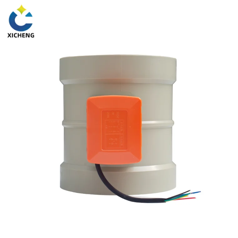
An electric valve is two subassemblies joined at a flanged interface: the valve body below, which contains the sealing element, and the electric actuator above, which provides the turning or lifting force. On a duct that same pair assembles as an electric air valve: a motorized blade body with the actuator head that positions it in the airstream. The body is chosen for the line conditions and the actuator for the torque, travel, voltage, and control the system demands. Because the two are matched rather than bonded, the same body can be motorized or left manual, and many actuators follow the ISO 5211 mounting standard so bodies and drives mate across product ranges.
How an Electric Valve Works
Motor and gear train movement
At the core of an electric actuator is a small electric motor feeding a gear train that converts high motor speed into the slower, high-torque movement the valve needs. Quarter-turn designs rotate the output drive 90 degrees, which suits a ball, a butterfly, or a damper blade; multi-turn designs drive a rising or non-rising stem for gate, globe, and knife gate valves. Limit switches stop the drive at the fully open and fully closed positions, and an over-torque switch backs the drive off if it seats against a jam.
Signal interpretation
An on/off actuator accepts a simple control voltage — a 24 V or 220 V signal that tells the motor to run to one end of travel and stop. A modulating actuator instead reads a positioning signal and holds a proportional position. The common control standard is a 4–20 mA current loop, in which 4 mA means fully closed, 20 mA means fully open, and 12 mA sits the valve at 50 percent; 0–10 V DC is an equally common alternative in building automation.
Position in the control loop
In an automated process the electric valve is the final control element in a loop: a sensor measures pressure, temperature, or flow, a controller compares the reading with a setpoint, and the actuator repositions the valve to bring the process back on target. The valve turns the controller’s 4–20 mA or digital command into physical movement, which is why selection starts with the signal the system will actually send.
On/Off or Modulating: the First Decision
The first question about any electric valve is whether it must isolate or regulate. An on/off electric valve travels to an end stop and stops, and it is sized as a shutoff device; a modulating electric valve can stop anywhere across its travel and is sized as a throttling device. The two behave differently in a control loop, so the section on on/off versus modulating valves explains the choice before the valve type is picked.
Types of Electric Valves
Different bodies suit different media and duties. An electric motor can be mounted on any quarter-turn or multi-turn valve, so the product range follows the valve families. Table 1 summarises the six common types.
Electric Ball Valve
The actuator rotates a ball with a bore through its centre. A quarter turn aligns the bore with the pipe to open and presents the solid face to close, giving excellent shutoff with low seating torque. Electric ball valves are the standard for on/off isolation in water, gas, and chemical lines, and in modulating form they throttle clean, particle-free media.
Electric Butterfly Valve
A butterfly body uses a disc that pivots across the bore, so the actuator needs only a quarter turn and a modest torque even in large diameters. That butterfly body is covered in full by the electric butterfly valve guide, including the wafer, lug, and flanged variants and the throttling window. The simple, light structure keeps cost down and makes the electric butterfly valve the usual choice for large pipes, air ducts, and low-pressure services where a full-bore ball would be oversized.
Electric Gate Valve
The actuator drives a rising stem that lowers a gate between two seats and lifts it clear for a full, unobstructed passage. Gate valves give the lowest pressure drop of any full-open position but move slowly over many turns, so the electric version is chosen where a large line needs a positive, full-opening isolation without pressure loss.
Electric Globe Valve
A globe body forces the flow to change direction through a seat, and the actuator presses a plug or disc into that seat with a linear stroke. The deliberate restriction gives fine, repeatable throttling, which makes the electric globe valve the preferred choice for high-accuracy process lines, sampling systems, and dosing stations.
Electric Knife Gate Valve
The knife gate mounts a flat, sharp-edged gate on a linear actuator to slice through and shut off flow in lines carrying slurries and solids — sewage, cement, fly ash, and abrasive suspensions. The electric drive removes the heavy manual effort such media demand.
Electric Damper Valve
An electric damper valve is a blade or louvre element in an air or gas duct, driven by an actuator to regulate airflow. The general-purpose duct-damper form of that blade, used on fresh-air intakes, zone branches, and supply duct, is developed in the electric motorized damper guide. Damper valves are critical parts of HVAC systems, regenerative thermal oxidizers (RTOs), VOC gas treatment facilities, and exhaust heat recovery, where they modulate or isolate ducted air that a piped valve cannot handle.
| Type | Motion | Sealing or regulating element | Best duty | Typical use |
|---|---|---|---|---|
| Electric ball valve | Quarter-turn | Bore-drilled ball between seats | On/off shutoff | Water, gas, chemical isolation |
| Electric butterfly valve | Quarter-turn | Disc pivoting across the bore | Large-diameter on/off and modulation | Big pipes, air ducts, low pressure |
| Electric gate valve | Multi-turn | Gate lifted between two seats | Full-bore positive isolation | Large lines, utility headers |
| Electric globe valve | Linear | Plug or disc into a seat | High-accuracy throttling | Process lines, dosing, sampling |
| Electric knife gate valve | Linear | Sharp-edged gate | Slurry and solids shutoff | Sewage, cement, fly ash lines |
| Electric damper valve | Quarter-turn | Blade or louvre in a duct | Ducted air regulation | HVAC, RTO, VOC treatment |
Electric Valve vs Solenoid Valve
The most common specification question is how a motorized electric valve differs from a solenoid valve, because both turn an electrical signal into valve movement. The two are built on different principles: an electric valve uses a motor and gear train, a solenoid valve uses an electromagnetic coil and plunger. The difference decides which one fits the application, and the engineering background of the solenoid valve is worth reading on the mechanics.
Actuation Method
An electric valve opens and closes with an electric motor, which converts electrical energy into high-torque rotary or linear motion through a gear train. A solenoid valve actuates directly with an electromagnetic coil: current through the coil creates a magnetic field that pulls a metal plunger against a spring, and the plunger moves the sealing element. There is no motor, gear, or intermediate motion in a solenoid — the coil is the actuator.
Speed and Duty
A direct-acting solenoid valve responds in 5 to 10 milliseconds, which makes it the choice for frequent, fast switching between open and closed. A motorized electric valve takes seconds to travel between positions, and repeated rapid cycling can overheat the motor, so an electric valve needs a minimum off time between strokes and suits slower, less frequent moves. Pilot-operated solenoid valves run between 15 and 150 milliseconds depending on size.
Flow Range
A typical direct-acting solenoid exerts about 15 N of force, so its orifice sizes and working pressure differences stay small; solenoid valves suit small-bore lines, low pressures, and low flow rates. An electric valve’s gear train multiplies motor torque, so it handles large diameters, high pressures, and full process flows that a solenoid cannot move.
Power-Failure Behaviour
A solenoid valve is spring-returned: when power drops, the spring drives it to its de-energized state, normally closed or normally open as specified. An electric valve holds its last position on power loss because the motor stops where it was; if the system needs the valve to fail to a safe position, a fail-safe actuator must be fitted. Neither behaviour is right by itself — the specification must say what “safe” is for the process.
Voltage-Shock Tolerance
The solenoid’s coil is an electromagnet, and a voltage surge can overheat or break down its winding. An electric valve’s motor is more tolerant of voltage shock, which is one reason tough industrial sites favour motorized valves outside the instrument cabinet.
Which One to Choose
Choose a solenoid valve for a small line that must switch fast and often — purge air, pilot gas, dosing, automatic irrigation. Choose an electric valve when the line is larger, the flow higher, or the position must be held or throttled at an intermediate opening. Table 2 collects the comparison.
| Factor | Electric valve (motorized) | Solenoid valve |
|---|---|---|
| Driving force | Motor and gear train | Electromagnetic coil and plunger |
| Speed | Seconds per stroke | 5–150 ms |
| Cycling | Frequent cycling can overheat motor | Built for frequent switching |
| Flow range | Large bores, high pressure | Small bores, low pressure difference |
| Position control | Holds any opening, throttles | Open or closed only |
| Power loss | Stays in last position | Springs to normal state |
| Voltage shock | Motor tolerant | Coil can burn out |
Where the application needs fast, spring-return behaviour, the solenoid valve product page shows the corrosion-resistant range; where it needs motorized torque and throttling, the electric valves range is the match.
On/Off vs Modulating Electric Valves
A control system can ask an electric valve for one of two behaviours, and the body and actuator are chosen differently for each. The distinction between a shutoff valve and a control valve is treated in the engineering source on control valves; the practical summary follows.
On/Off Electric Valves
An on/off electric valve travels to one of two end stops, fully open or fully closed, and stays there. The actuator switches on, runs the drive to the limit switch, and shuts off. On/off duty suits isolation, safety shutoff, and changeover — any point in a plant where a line is either passing flow or sealed. Ball, gate, and knife gate bodies are the usual on/off choices because their seats are built to shut tight rather than to throttle.
Modulating Electric Valves
A modulating electric valve can stop anywhere across its travel and hold that position against the flow. It reads a positioning signal — a 4–20 mA loop or a 0–10 V signal — and drives to the matching angle or stroke. The classic mapping is 4 mA fully closed, 20 mA fully open, and 12 mA at 50 percent, with every milliamp mapping to a proportional opening. Modulating duty suits flow, pressure, and temperature regulation where the valve must sit at intermediate openings for long periods; globe and butterfly bodies lead here, and a modulated ball valve follows where the media are clean.
Intelligent and Explosion-Proof Variants
Above the basic pair sit two specialized classes. An intelligent electric valve carries a local controller that accepts setpoints, runs its own position loop, and reports status to a PLC or DCS, so it does not depend on a remote loop card. An explosion-proof electric valve is built and certified for flammable atmospheres, with a flameproof enclosure rated for the site — a typical classification is Exd IIB T4 — so it can sit inside a hazardous-area boundary without igniting the surrounding gas.
Control and System Integration
An electric valve earns its place in a plant by plugging into the control system, and the connection is specified in three parts: the signal that drives it, the feedback it returns, and the mounting and protection it must meet. The engineering reference on actuators sets the wider context for the drive side.
Control Signals
On/off valves need a simple contact or a 24 V or 220 V control signal that runs the motor to an end stop. Modulating valves need an analogue or digital setpoint: the 4–20 mA current loop is the process-industry standard, 0–10 V DC is common in building automation, and modern actuator ranges add bus-based commands from a PLC or DCS. Every modulating loop is backed by a sensor — pressure, temperature, or flow — so the controller has a real value to regulate against.
Position Feedback
Every valve worth automating reports where it is. The actuator carries position switches for open and closed status, and modulating units return an analogue position signal so the controller can confirm the valve reached its setpoint. This feedback closes the loop and lets the control room see a stuck or slow valve instead of assuming the line is set.
Mounting, Protection, and Duty Rating
The actuator mounts to the body on a standard interface — ISO 5211 is the common pattern for quarter-turn units — so actuator and body can be matched independently. Protection against water and dust follows the IP code, with IP67 a common outdoor rating, and explosion-protected units carry ATEX or IECEx Exd-rated certificates for hazardous areas. The duty rating and minimum off time come from the motor data, so the actuator is checked against the real number of strokes per day before it is ordered.
How to Select an Electric Valve
Selection runs from the line outward: the fluid and its conditions choose the body, the body and the service choose the actuator, and the control system chooses the electronics. Working through the six steps avoids the classic mistakes — an actuator that cannot close against line pressure, or a body that corrodes where the duct does not.
1. Know the Line Conditions
Start with the media: its chemistry, corrosivity, solids content, temperature, pressure, and maximum flow. A valve that handles water cannot be assumed to handle an acid fume, and a valve specified for gas pressure may not seal a vacuum line. List the worst-case operating point, not the normal one, because the torque and material choices follow it.
2. Choose the Valve Type
Match the body to the duty from the type table: a ball or gate for shutoff, a globe or butterfly for throttling, a knife gate for solids, a damper for ducted air. The electric actuation comes after the body is fixed — a body wrong for the media stays wrong whether the handle is powered or manual.
3. Size the Actuator Torque
The actuator must deliver enough torque to seat and unseat the valve against line pressure. The dedicated electric valve actuator guide walks through how that torque is turned into a motor, gear train, and duty specification. Start from the valve’s published torque requirement and apply a safety factor: standard service calls for 1.3 to 1.5 times the required torque, while severe service — high viscosity, elevated pressure, or extremes of temperature — may need 1.7 times or more. A Cv (flow coefficient) check confirms that the selected valve passes the required flow at the available pressure drop.
4. Power and Voltage
Decide the actuating supply before ordering. Common choices are 24 V DC for instrument-grade and building automation duty and 110–220 V AC for industrial power circuits. The choice fixes the control interface: AC units usually pair with contact or relay start, DC units with PLC analogue cards and battery-backed supplies.
5. Fail-Safe and Power-Failure Behaviour
Decide what the valve must do when power disappears. A standard electric valve holds its last position, which is safe only if the process tolerates it. Fail-safe electric actuators add a spring-return mechanism or an integrated backup capacitor that drives the valve to a predetermined safe position — normally closed, normally open, or vented — when main power fails, making them the rule on fuel, toxic, and flame-critical services. Where a fuel line also needs a positive hand-operated shutoff for proving isolation, the manual gas valve guide shows the manual companion to powered control.
6. Materials
Choose the wetted materials to match the media and the surrounding plant. Cast iron suits general water and gas, stainless steel suits corrosive liquids, and for corrosive fume and duct duty a PP-bodied electric valve keeps corrosion resistance through the valve exactly as the duct run provides it. The polypropylene properties guide explains how PP holds under the chemical exposure fume lines carry, and the electric valves range lists bodies and actuators as matched pairs for that duty.
Electric Valves in Duct and Fume Service
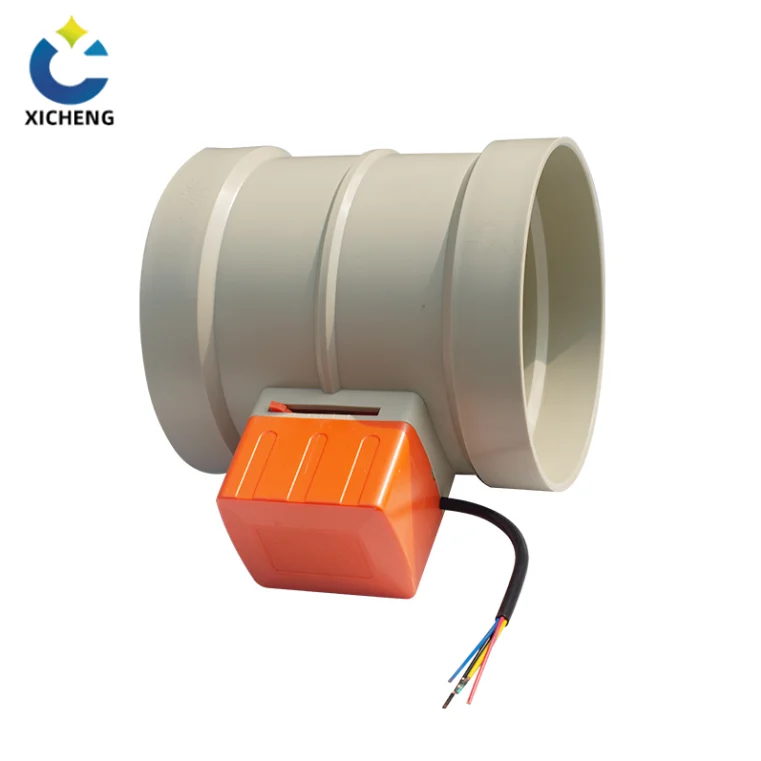
Where the line is a duct rather than a pipe, the electric valve arrives as an electric damper valve or an electric air valve: a motorized blade or louvre that regulates or isolates airflow in a ventilation system. This is the duty where a plastic-bodied valve earns its keep, because the fume being moved is often the very chemistry that attacks metal.
Electric Damper Valves in Ventilation, RTO, and VOC Duty
Motorized dampers are the control elements of air systems: HVAC balancing, regenerative thermal oxidizers, VOC gas treatment, and exhaust heat recovery all use them to modulate airflow and isolate sections. The blade closes a duct that no piped valve would ever fit, and the electric drive both positions it for balancing and closes it fast for ventilation safety. The exhaust-duct edition of that blade, with code-mandated shutoff, defined fail positions, and corrosive-fume bodies, is the electric exhaust valve guide.
Corrosion Resistance and PP Electric Valve Bodies
On a fume extraction line the valve body faces the same aggressive chemistry as the duct. A PP electric valve keeps corrosion protection continuous through the take-off, the blade, and the housing, where a cast iron or carbon steel body would become the weak link the maintenance log records. The electric air valve product page covers motorized plastic bodies for duct duty, and the electric valves range carries the wider body family.
Working with the Plastic Duct System
The valves bolt into the same PP and PVC world as the ducting. The plastic duct damper guide shows how dampers integrate with the duct run, the manual air valve guide is the manual counterpart for unpowered take-offs, and the manual bleed valve guide pairs with the electric unit where a low point must be vented before opening. A powered valve on a fume line is usually backed by a manual shutoff so the section can be proven dead with the power off.
Installation, Operation and Maintenance
A correctly sized electric valve that is installed carelessly, operated without thought, or never maintained will fail a plant faster than an undersized one. The practices below follow the standard routines for motorized valve duty.
Installation and Commissioning
Install the valve in the orientation the body allows, with a clean flanged or threaded connection and no pipe strain pulling on the body. After wiring, commission the actuator: set the travel stop and over-torque controller so the drive stops accurately at the fully open and fully closed positions, and verify each end-stop under power before the line is pressurized. A valve that stops short of position wastes motor strokes and leaks through the seat.
Operation
Set the actuator’s local/remote selector for the duty: LOCAL for on-site opening during commissioning and testing, REMOTE for supervision from the control room, then confirm open and closed status from the position indicators rather than assuming. Where a large valve is opened against high differential pressure, open the bypass first and close it once the main line is balanced. Run an on/off valve fully open or fully closed: throttling a shutoff valve wears its seating and leaves it unable to close tight, and a halfway position buys the process nothing.
Maintenance Routine
Inspect the valve and actuator regularly for leaks, corrosion, loose wiring, and motor warmth. Clean and lubricate the moving parts at the manufacturer’s intervals, and re-check the travel and torque settings after any service. If the drive fails, stops mid-travel, or the motor runs hot, stop and call the maintenance team instead of forcing the handwheel — the actuator on an electric valve is easier to damage by hand than to repair.
Electric Valve FAQ
What is an electric valve?
An electric valve is a valve assembly driven by a motorized actuator. The actuator mounts on a valve body and turns or lifts the sealing element — a ball, disc, gate, or damper blade — in response to a switch or a control signal. An on/off electric valve travels to a fully open or fully closed position; a modulating electric valve can stop at any opening and throttle the flow.
What is the difference between an electric valve and a solenoid valve?
An electric valve is driven by an electric motor and gear train, moves slowly in seconds per stroke, carries large bores and high pressures, holds any position, and stays where it was on power loss unless a fail-safe unit is fitted. A solenoid valve is driven directly by an electromagnetic coil and plunger, switches in milliseconds, suits small bores and low pressure differences, and springs back to its normal state when power drops. Solenoids suit frequent, fast switching; electric valves suit torque, throttling, and PID-modulated process control.
How much torque does an electric valve actuator need?
Start from the valve’s published torque requirement and apply a safety factor of 1.3 to 1.5 times for standard service. Severe service — high viscosity, high pressure, or extremes of temperature — may require 1.7 times or more. A Cv (flow coefficient) check confirms the valve passes the required flow at the available pressure drop.
What happens to an electric valve during a power failure?
A standard electric actuator stops where it was and the valve holds its last position. If the process cannot tolerate that, a fail-safe actuator must be fitted: a spring-return mechanism or an integrated backup capacitor drives the valve to a predetermined safe position — normally closed, normally open, or vented — when main power fails.
Can an electric valve throttle?
Yes, if it is a modulating type sized for the duty. A modulating electric valve stops anywhere across its travel and holds that opening, which suits flow, pressure, and temperature regulation. An on/off electric valve should be run fully open or fully closed; throttling a shutoff valve wears its seating and leaves it unable to close tight.
Key Takeaways
An electric valve is a motor-driven actuator mounted on a valve body: the body is chosen for the line conditions and the actuator for the torque, travel, voltage, and control the system demands.
Six bodies cover the duty map — ball and gate for shutoff, globe for throttling, butterfly for large bores, knife gate for solids, damper for ducted air — and the actuator is matched to the body, never chosen first.
Solenoid and electric valves are different tools. The solenoid springs back fast and resets on power loss; the electric valve holds its last position and throttles. Choose on speed and cycling versus torque and process control, not on whichever term lands first in a search.
Size the actuator torque with a safety factor — 1.3 to 1.5 times required in standard service, 1.7 times or more in severe service — and define the power-failure behaviour before ordering, because holding the last position is rarely the safe answer by itself.
On corrosive fume and duct duty, choose the body to match the duct: a PP electric valve keeps corrosion resistance continuous through the take-off, where a metal body becomes the weak link the maintenance log records.
For a powered valve specification on a plastic duct system, the engineering team can size the body, actuator torque, and control interface together against the actual line conditions.
