
An electric valve actuator is the motor-driven unit that opens, closes, or positions a valve. It bolts onto the top of the valve body and converts electrical energy into the torque or thrust that turns a ball, swings a butterfly disc, or lifts a gate, so the valve responds to a switch, a control signal, or a program instead of a hand on a handle. On this site the actuator family sits alongside the plastic duct damper, the manual air valve, and the electric valve guides — the powered and the manual counterparts of the same duct system.
The actuator deserves its own look, because it is the part that decides how fast a valve moves, how much torque it delivers, how precisely it holds an intermediate opening, and what it does when power disappears. A valve body that is ideal for the line can still fail in service if the actuator above it is undersized, or the wiring, or the switch that stops it at the end of travel. This guide explains how an electric valve actuator works, the types by motion, how it compares with pneumatic and manual operators, how control systems drive it, and how to select one by torque, duty, power, protection, and fail-safe behaviour. For a complete motorized assembly on a plastic duct system, the electric valves product page shows valves and actuators as matched pairs.
What Is an Electric Valve Actuator?
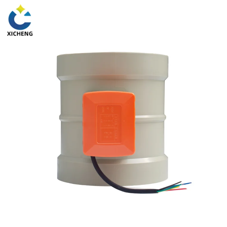
An electric valve actuator is a self-contained drive assembly — motor, reduction gear train, end-of-travel switches, and wiring — mounted on the top of a valve body. It converts electrical energy into the torque or thrust the valve needs, and it is the interface between the control system and the process flow: the system sends a command, and the actuator turns that command into movement of the valve stem. The actuator, not the body, decides how fast the valve travels, how much force it applies, and what happens on a power failure, which is why selection starts with the actuator’s torque rating, travel, and control interface.
Definition and Role in an Automated Valve
An electric valve actuator does three jobs in sequence. It receives a command — a contact closure, a 24 V signal, a 4–20 mA position value, or a fieldbus word. It amplifies that command through a motor and gear train into a mechanical movement. And it stops at the commanded point, holding the seat against the pressure. Suppliers describe the whole package as a motor-operated valve (MOV), because the actuator is what makes the valve “operated”. The valve body handles the flow; the actuator handles the motion.
Rotary and Linear Output Motion
Quarter-turn and multi-turn rotation
An electric valve actuator for a ball, butterfly, or plug valve rotates its output drive through 90 degrees — a quarter turn — between fully open and fully closed. Quarter-turn actuators mount to the valve through the ISO 5211 standard, and the drive coupling sets onto a square or diamond valve stem. Multi-turn electric valve actuators instead turn through many revolutions to drive the rising or non-rising stem of a gate, globe, or knife gate valve, and they mount through the ISO 5210 standard. The two families are not interchangeable: put them on the wrong valve type and the travel, the gearing, and the end-stop behaviour all miss.
Linear (reciprocating) stroke
Linear electric valve actuators push or pull the valve stem straight up and down for globe, angle, and control valves. Where a rotary actuator turns a ball, a linear actuator lifts a plug or a disc off its seat. Electric linear actuators use a threaded screw drive: the motor rotates a rod and the stem travels along its thread. Because many revolutions between the top and bottom positions allow finely divided movement, the screw drive is what gives electric linear actuators the precise positioning that throttling control valves require.
The Mounting Interface to the Valve
At least three parts join actuator to valve: the output drive that engages the stem, the stem connection, and a flange that bolts the actuator to the valve top. Flange size and fastener pattern follow the torque class of the actuator, so the mounting standard is what lets one actuator range move across several valve sizes. On a small plastic duct valve the actuator often screws straight onto the valve top assembly; checking the flange dimension before ordering avoids a mismatch at installation.
What an Actuator Adds over a Handwheel
An actuator’s value is remote, repeatable, and reportable operation. It can be switched from a control room, scheduled by a timer or PLC, and repositioned every few seconds for modulating control, all without a person at the valve. It reports back its position, torque faults, and running state to the control system, which a handwheel cannot do. The handwheel remains as a manual override for commissioning and emergencies, but the actuator takes the daily labour off the maintenance crew. The wider concept of an actuator as a power-transmitting mechanism is covered by the actuator reference.
How an Electric Valve Actuator Works
The working core of an electric valve actuator is a small electric motor coupled to a reduction gear train. The motor spins fast at comparatively low torque; the gear train converts that high-speed rotation into the slower, high-torque output the valve stem needs. Understanding the chain — motor, gears, switches — explains almost every operational fact about these units, from why they are quiet to why duty cycle limits them.
Motor, Reversing Contactor and Gear Train
The motor and reversing control
Most industrial electric valve actuators use an asynchronous three-phase AC motor, with single-phase AC and DC motors common on smaller and building-automation units. The motor develops its highest torque from standstill, which is exactly when a valve is hardest to move — breaking a settled ball or disc out of its seat. A reversing contactor, or a set of thyristors on the control board, swaps the direction of rotation for opening and closing, and it can live inside the actuator housing or in a remote motor-control cabinet.
Gear ratios trade torque against speed
The same actuator body is typically offered with several gear ratios, so the torque and speed of one housing vary inversely with the reduction. A catalog line might list 50 in·lbf with a 3-second cycle time, 100 in·lbf with 6 seconds, and 200 in·lbf with 12 seconds — all the same housing, different gearing. Selecting the slow, high-torque ratio or the fast, low-torque ratio is a genuine engineering choice, made after the required torque is known, not before.
Self-locking worm gearing
Many quarter-turn designs reach the valve through worm gearing, which is self-locking. The worm can drive the gear wheel, but the gear wheel cannot drive the worm backwards. Because of that, the valve holds its position against line forces with the motor idle — the gear set holds it, not a running brake or a holding clutch — which is one reason electric actuators are quiet and energy-efficient at rest.
Limit Switches and Torque Switches
End-of-travel is handled by switches, not by an operator’s eye. Limit switches on an electric valve actuator are activated by adjustable cams mounted on the drive shaft, and they cut the motor at the fully open and fully closed positions; the cams can be re-set to fine-tune where the actuator stops. The drive can also be stopped on torque: a torque switch senses the seating resistance and cuts the motor when the drive meets it. End positions are therefore set one of two ways — limit seating, which stops at a switched position of the drive, or torque seating, which stops when the seat is pressed home. The same torque sensing doubles as mid-travel overload protection, so if a seized stem or a foreign object blocks the closure, the drive backs off instead of bending the linkage.
Feedback and Position Sensing
An electric valve actuator reports its state as well as obeying commands. Many carry a position transmitter that returns a 4–20 mA signal proportional to stem position, and the limit and torque switches offer dry contacts for position and fault status to the control system. Most units add a visual indicator — a mechanical dial or an on-screen display on the housing top — so a walk-past operator can read valve position without any electronics. On smart, non-intrusive units the position and torque settings live in memory and the feedback relays are programmed to the site’s logic rather than set on fixed cams.
The motor’s heat generation caps how often an electric valve actuator may be cycled, and the duty-cycle and thermal rules for that choice are covered with actuator selection below.
Types of Electric Valve Actuators by Motion
Electric valve actuators are usually classified by the motion they produce, because the motion must match the valve. Rotary valves — ball, butterfly, plug, damper — need rotary movement; rising-stem valves need rotating or straight-line thrust. Picking the motion class first, then the torque, quickly narrows the market. Table 1 summarises the three families.
Quarter-Turn (Part-Turn) Actuators
A quarter-turn electric valve actuator rotates its output drive 90 degrees, taking a ball, butterfly, or damper blade from fully closed to fully open. The valve side of that pair is in the electric butterfly valve guide, which covers the quarter-turn disc body, its connections, and the throttling window. It is the most common family in duct and process duty because the valves it drives are the most common, and it mounts to the valve through the ISO 5211 interface with a square- or diamond-bore drive coupling. Cycle times are typically seconds, and the same actuator range covers a wide torque band by changing the reduction gear. Quarter-turn units dominate ventilation dampers and the small motorized ball valves used for isolation. The ventilation-damper quarter-turn drive, with its torque, travel-time, and duty-cycle ratings, is the electric motorized damper, treated in a guide covering fresh-air, zone, and supply service. That quarter-turn damper duty is exactly the electric air valve: a self-locking motorized blade that modulates duct airflow on a position signal.
Multi-Turn Actuators
A multi-turn electric valve actuator turns through many revolutions to drive a rising-stem or non-rising-stem gate, globe, or knife gate valve. Its output is a full rotating shaft, and it is used where a single quarter turn cannot lift the closure member far enough — large bores, high differential pressure, and stem sealing duties. Mounting follows ISO 5210, and the gearing multiplies torque continuously over many turns, which is how relatively small motors move large gate valves. Multi-turn units are the workhorse of water, wastewater, and process isolation.
Linear Actuators
A linear electric valve actuator pushes or pulls the valve stem along a straight stroke for globe, angle, and control valves. Because the closure member lifts off its seat rather than rotating, linear actuation gives fine, incremental positioning — the screw drive divides many motor revolutions into a short, precisely controlled stem travel, which is why modulating control valves are usually linear. The actuator family carries its own mounting convention, distinct from the quarter-turn and multi-turn rotary interfaces.
| Actuator family | Typical valve bodies | Mounting standard | Travel | Best suited for |
|---|---|---|---|---|
| Quarter-turn (part-turn) | Ball, butterfly, plug, duct damper | ISO 5211 | 90 degrees | Duct dampers, fast isolation, building automation |
| Multi-turn | Gate, globe, knife gate (rising stem) | ISO 5210 | 360 degrees + multiple turns | High-torque isolation, large bore, water and process lines |
| Linear (reciprocating) | Globe, angle, control valves | Screw-drive linear convention | Straight stroke | Precise throttling and modulating control |
The selection rule is simple: match the actuator family to the valve movement before anything else. A quarter-turn actuator on a rising-stem gate valve can neither lift the disc nor reach the end stops, and a multi-turn actuator on a ball valve would unwind its drive into the seat. The electric valves product range lists each actuator family with the bodies it is matched to.
Electric vs. Pneumatic vs. Manual Actuators
An electric valve actuator competes in the market with pneumatic actuators, which are driven by compressed air, and with manual operators, which are driven by a person. Each has a legitimate place, and the selection question is asked constantly in process plants. The engineering background of valve actuators is worth reading on how the families relate before the choice below.
Pneumatic Actuators at a Glance
Pneumatic actuators use compressed air to move a piston or diaphragm. Rotary pneumatic styles include scotch yoke, rack and pinion, and vane designs; linear styles include diaphragm and piston-cylinder types. A spring-return pneumatic actuator parks in a defined fail position when air supply is lost, and a solenoid valve shifts the air to open or close the valve. Compressed air gives high force and speed in a compact footprint, and force and speed are semi-independent of each other — more force means a larger cylinder and a slower stroke. The cost story turns on the supply: a compressor, air tubing, solenoid wiring, maintenance, and the electricity to run the compressor all add up, so pneumatic is most economical where a compressor already exists with spare capacity.
Why Choose Electric
An electric valve actuator wins on precision, energy economy, and independence from an air system. High-quality screws and anti-backlash mechanisms position the output within ten-thousandths of an inch on precision units and within a few thousandths of an inch on standard ones, which is why modulating and control-valve duty is dominated by electric and electro-hydraulic units. It draws power only when it moves, so idle actuators add no running cost. It needs no compressor, no tubing, and no instrument air verification, and it produces no emissions, which matters more as emission rules tighten worldwide.
An electric valve actuator also automates directly: the same control-network signals that run a DCS or PLC drive it from off site, where a pneumatic valve needs an extra I/P converter to translate an electrical command into air pressure. The trade-offs are that thrust and speed cannot be had together — an electric valve actuator gives more thrust only at slower speeds and less thrust at high speeds — and the initial sizing must be right, because increasing thrust after installation means buying a larger actuator.
Manual Operators
Manual operators have not disappeared, and they remain the emergency and economics choice on many lines. A basic lever runs small quarter-turn valves, a geared handwheel with a gearbox increases mechanical advantage on larger butterfly valves, and a chain wheel brings an out-of-reach actuator down to ground level for operation. Manual valves fitted with limit switches report their position to the control system without any automation of the valve itself. On this site the manual family is covered in the manual air valve and manual valve actuator guides, and a manual shutoff often backs up a powered valve so a section can be proven dead by hand. Where a fuel or gas line needs a positive hand-operated isolation for proving, the manual gas valve guide shows that companion.
| Factor | Electric actuator | Pneumatic actuator |
|---|---|---|
| Power source | Electric motor, no supply gas | Compressed air from a compressor |
| Positioning precision | Fine; anti-backlash gearing for throttling | Good; needs a positioner for smooth control |
| Speed | Seconds per stroke, more torque at slower speeds | Fast; speed adjustable with air throttling |
| Installation | Power cable only; separate power from signal | Compressor, tubing, solenoid, plus wiring |
| Operating cost | Low; power drawn only while moving | Higher; compressor electricity and air leakage |
| Emissions | Zero at the actuator | Indirect; compressor energy and purge air |
| Automation | Direct network and analog control | Needs an I/P converter for electric signals |
| Fail position | Holds position; spring or backup for forced fail | Spring return gives a fail position for free |
Which Fits Duct and Fume Plants
On plastic duct and fume systems the electric valve actuator is usually the right choice, because the typical installation has no instrument-air network and does not want one. The valves are small, low-torque units whose motor draws more when it is not running, and the same 0–10 V or 4–20 mA signals that the fume-control PLC already uses drive the actuator directly. Where a take-off must simply be open or closed without automation, the manual units linked above do the same wiring-free job.
How Electric Valve Actuators Are Controlled
The control interface is the second half of an electric valve actuator’s specification, after torque. The same hardware can behave completely differently depending on whether it listens for a contact closure, a 4–20 mA position value, or a fieldbus word — so the actuator must be ordered to match the signals the control system actually sends. This section covers the control, feedback, and loop options detailed in the industry’s valve-basics references.
Local and Remote Control
Local controls are mounted directly on the actuator housing — an open/close selector, a hand-auto switch, and position indication — so an operator standing at the valve can run it without the control room. Remote controls drive the actuator from a PLC, DCS, control panel, or building management system. Proper installations provide both: local for commissioning and maintenance, remote for normal operation, with a local/remote selector that prevents the control room overriding a man at the valve.
Discrete Open/Stop/Close Signals
The simplest remote scheme is discrete control: an open signal, a stop signal, and a close signal sent by relays, pushbuttons, or PLC outputs to the actuator’s logic. Control power is typically 24 V DC or 110 V AC, and some actuators include a built-in control power transformer so the contact-level signal from the PLC can switch the higher motor voltage. Discrete signals suit on/off isolation valves and are also used where an intermediate position is reached by timing the travel.
Analog 4–20 mA Positioning
Modulating duty uses an analog positioning signal. The standard is a 4–20 mA current loop in which 4 mA means fully closed, 20 mA means fully open, and a value between them sets the valve at the proportion between the two — 12 mA parks the valve at 50 percent. The 0–20 mA range is deliberately avoided because 0 mA can be misinterpreted as a lost signal. The same current loop is often the output of a flowmeter upstream of the valve, so the valve regulates flow directly from the measurement. Building automation frequently uses 0–10 V DC in place of the current loop.
Fieldbus and Digital Bus Control
On modern plants several actuators are wired to one control network, where a digital bus carries setpoints, status, and diagnostics to every unit. Fieldbus, or two-wire digital communication, replaces dozens of discrete wires with one network segment. The protocol must match between the actuator and the system: common options are Foundation Fieldbus, Profibus, Modbus RTU and Modbus TCP/IP, HART, Ethernet/IP, DeviceNet, and BacNet. Before ordering, confirm which protocol the site standardises on, because an actuator wired with the wrong protocol cannot talk to the controller at all.
Feedback and Status Signals
Feedback is the information flowing back from the electric valve actuator to the control system. Analog feedback provides a 4–20 mA output proportional to valve position, and some actuators also output a 4–20 mA signal of output torque. Discrete feedback surfaces status relays — position reached, torque fault, general fault, running, or intermediate position — and the limit and torque switches themselves are available as dry contacts. Visual feedback is the mechanical or on-screen position indicator every unit carries. On intelligent actuators the feedback relays are programmable, so one model adapts to whichever status the customer’s logic needs.
Positioner and PID loop
Where the process must hold a precise opening against changing pressure, the actuator gains a positioner. A positioner compares the demanded 4–20 mA value with the measured stem position and drives the motor until the two match, correcting for drift and load. Intelligent actuators can run their own PID logic and tune the correction, so the actuator becomes a self-contained final control element rather than just a motor that runs to an end stop. The control-loop wiring and signal behaviour are covered more fully in the control valve reference.
How to Select an Electric Valve Actuator
Selection runs in a fixed order: match the motion to the valve, calculate the torque the valve demands, add a safety factor, then check the duty cycle, power supply, environment, and fail-safe behaviour. Working through these steps avoids the classic failures — an actuator that stalls mid-stroke, a motor that overheats on frequent cycling, or a valve that parks in the wrong position on a power outage. The checks below follow the sizing practice used across the actuator industry.
Match Actuator Motion to the Valve
The first decision is which actuator family the valve needs. A ball, butterfly, plug, or damper takes a quarter-turn actuator on the ISO 5211 interface; a rising-stem gate, globe, or knife gate takes a multi-turn actuator on ISO 5210; a globe or control valve needing precise lifting takes a linear unit. Choosing the wrong family is unrecoverable, so confirm the valve’s operator interface — stem shape, flange, and rotation direction — before any torque work begins.
Calculate Breakaway and Running Torque
Torque is the turning force the actuator must deliver to the valve stem, and the specification starts with the valve’s own torque figures. Breakaway torque is the force needed to move the valve from a fully closed or fully seated position, where friction between the seat and the closure member is highest, and it is normally the largest torque the actuator sees. Running torque is the lower force needed to keep the valve moving after it has started. Both figures vary with process conditions: higher pressure acting on the disc or ball raises the force required, high or low temperature changes friction and material stiffness, and flow rate changes the dynamic loading. Read the valve manufacturer’s torque table at the worst-case operating point, not the normal one. Practical actuator output torque spans from about 5 N·m on small instrumentation units up to 32,000 N·m and more on large industrial isolation valves, so the sizing discipline matters at every scale.
Apply a Safety Factor
Once the required torque is known, the actuator is chosen larger than the figure. The common rule is a safety factor of 1.2 to 1.5 times the required torque for standard service, with severe service — high viscosity, elevated pressure, solids in the flow, or temperature extremes — calling for 1.7 times or more, and actuators are normally rated to deliver 150 to 200 percent of the valve’s rated torque without damage. The torque safety factor mirrors the guidance applied across the valve range in the electric valve selection guide. Undersizing leaves the actuator unable to seat the valve and it stalls under load; oversizing past common sense puts excess stress on the valve stem and gears and speeds wear. Select the smallest actuator whose rated torque clears the requirement with the factor applied.
Check Duty Cycle and Motor Class
Duty cycle is how often the actuator is asked to operate, counted in operations per hour or per day. Twelve open/close actions per hour, for example, is a high-duty application. Every start draws a current surge and dumps heat into the motor, so a high start frequency demands a motor with higher thermal capacity, a better insulation class, and a higher start-rate rating to avoid overheating. Many electric actuators are rated below 100 percent duty: a unit with a 50 percent duty cycle and an 8-second stroke needs roughly an 8-second pause before its next move. Thermal protection trips at about 120 °C and resets once the motor cools, protecting the winding from the misuse a duty miscalculation causes. High-duty service typically uses squirrel-cage asynchronous motors with Class H insulation.
Power Supply and Voltage
Confirm the voltage available on site before ordering, because the motor winding is fixed at build. Common voltages are 12, 24, and 48 V DC and 24, 48, 120, and 240 V AC, with three-phase units for industrial networks at 380/440 V. DC versions are standard where battery-backed control is used; AC units pair with relay or contactor start. Universal-voltage actuators exist that sense and accept any of the common voltages, which simplifies stocking but should be confirmed by the catalog, not assumed.
Enclosure and Environmental Protection
The enclosure rating decides whether the actuator survives its surroundings. The familiar IP code comes from IEC 60529: IP67 protects against dust and against immersion up to 1 metre for 30 minutes, and IP68 extends that to deeper, longer submersion, which suits outdoor and wash-down duty. In North America the NEMA equivalents are common, with NEMA 4/4X for weatherproof outdoor duty and NEMA 7 for explosion-proof locations. Ambient temperature and humidity also matter — actuators are built to work across a wide temperature band, and the internal grease must suit the range, because cold grease raises torque demand and hot conditions challenge the motor’s heat budget.
Explosion Protection
Where an electric valve actuator sits in a classified hazardous area, it must carry the region’s explosion-protection certification. In the EU the ATEX directive (94/9/EC) governs flameproof and intrinsically safe equipment; in North America the National Electrical Code for the NEC and FM approval, and in Canada the CEC and CSA, apply. A flameproof (Exd) actuator contains an internal explosion so it cannot ignite the surrounding atmosphere, and the certification is granted by a notified body. Corrosion-resistant housings and seals, not just the motor, must carry the rating — the component evaluation covers the whole unit.
Fail-Safe and Backup Power
Finally, decide what the actuator must do when power disappears. A standard electric valve actuator stops where it was and holds its last position, which is safe only if the process can tolerate a valve frozen mid-position. If a defined fail position is required — fully closed, fully open, or vented — the actuator needs a fail-safe mechanism, usually a spring that drives the valve to the safe position, or in some designs an integrated backup capacitor. Where the actuator must keep operating normally through an outage, a UPS or a DC supply keeps the motor driving. The chosen failure position should be fixed before ordering, because it is usually not changeable after delivery.
Electric Valve Actuators for Duct and Fume Extraction
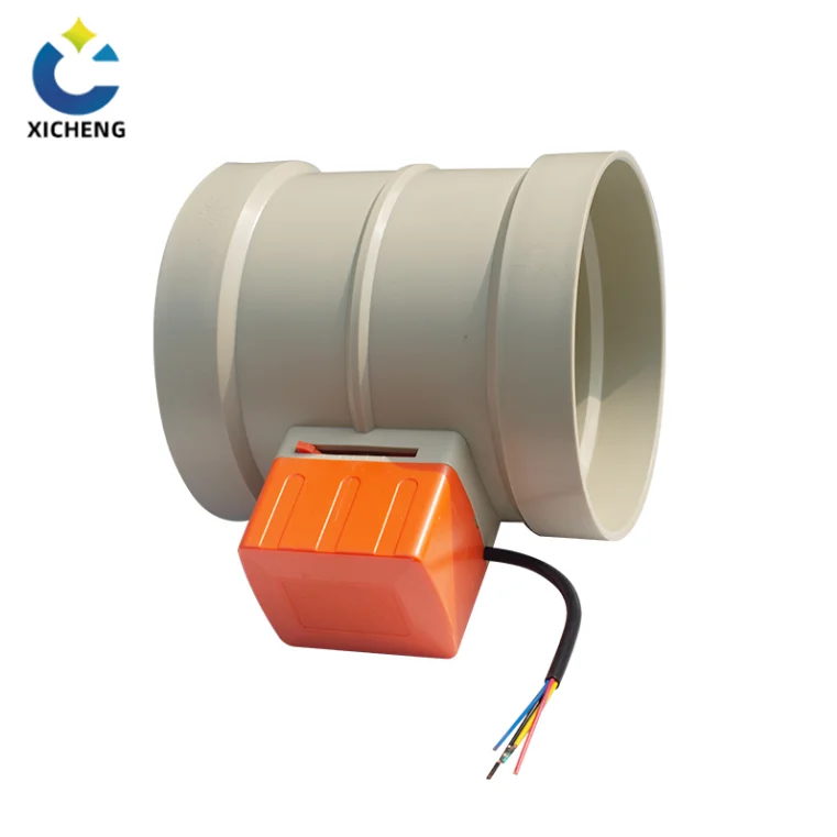
On a ventilation or fume extraction line an electric valve actuator usually arrives as the motor head on a plastic electric air valve or damper: a small motorized quarter-turn unit bolted to a PP or PVC valve body that isolates or modulates airflow. This is where the actuator’s independence from compressed air and instrument networks earns its keep, because the fume being moved is often the very chemistry that attacks a plant air system.
Why PP Duct Valves Suit Electric Actuation
A duct and fume plant is the natural home of the electric valve actuator precisely because it usually has no compressed-air network and does not want one. Air compressors, steel tubing, and oil-lubricated components are out of place beside corrosion-resistant ducting, while a small electric motor simply needs a 24 V or 220 V feed. The valves themselves are low-torque plastic bodies — motorized plastic electric air valves commonly cover duct diameters from about DN50 to DN315 — so a compact actuator travels their 90 degrees in seconds. The electric air valve product page shows motorized plastic bodies for this duty, and the electric valves range covers the wider actuator and body family.
Modulating Fume Control with 0–10 V / 4–20 mA
Fume extraction systems balance airflow continuously, and the modulating electric valve actuator is the element that does it. A modulating actuator board accepts a 0–10 V DC or 4–20 mA setpoint from a building management system or the process PLC, and positions the valve at the matching opening instead of just running to an end stop. That lets a scrubbing line track fan speed, lets a local exhaust hood keep face velocity constant as operators move, and lets an RTO or VOC treatment train isolate one bed while the others run. The motorized exhaust dampers behind that exhaust-hood control, including the code-mandated shutoff when the hood is idle, are developed in the electric exhaust valve guide. Where the control signal comes straight from a flowmeter, the actuator becomes a self-contained airflow regulator with no separate controller.
Matching Torque to Plastic Valves
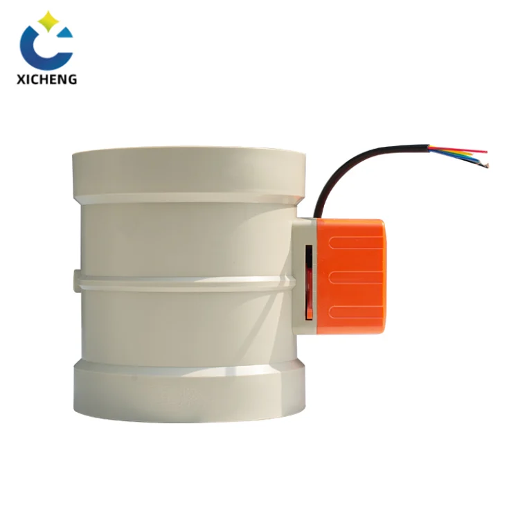
Plastic valve bodies need comparatively little torque, but the sizing discipline still applies. Start from the valve’s own torque table — a PP ball or butterfly valve lists its breakaway and running torque by diameter — and apply the 1.5-times safety factor already discussed. Differential pressure across a duct damper is usually low, so the torque driver is seat friction and sealing compression rather than line pressure, which lowers the required figure but does not remove it. The same torque rule that protects a metal gate valve protects a plastic damper from stem flex and seat damage.
Corrosion, Humidity and Washdown Environments
Fume and washdown duty brings moisture, acid-laden air, and aggressive cleaning chemicals, so the electric valve actuator’s housing and seals matter as much as its motor. An IP67 enclosure keeps water and corrosive droplets out of the terminal compartment, and the housing materials — polyester, PP, or anodized aluminium, depending on range — are specified to survive the same atmosphere the duct handles. Where the duct chemistry is severe, the polypropylene chemical resistance guide explains the exposure limits, and the body and actuator are selected as one corrosion-resistant assembly rather than a metal actuator bolted to a plastic body that it will outlast by the wrong margin.
Where an electric valve actuator handles the powered take-off, a manual companion usually backs it up: the plastic duct damper guide shows how dampers integrate with the duct run, the manual air valve guide is the unpowered counterpart for take-offs, and the manual bleed valve guide pairs with the electric unit where a low point must be vented before opening.
Installing, Commissioning and Maintaining an Electric Valve Actuator
An electric valve actuator that is sized correctly still performs badly if it is mounted, wired, or commissioned carelessly. Installation practice is largely standardised, and following it prevents the failures that follow improper setup — end stops that drive the valve into its seat wall, seal housings that let moisture in, and commissioning that leaves the torque or position setpoints wrong.
Mounting to the Valve
Mount the actuator through the correct interface: output drive set squarely onto the valve stem, and the mounting flange bolted down so the drive engages without side load. ISO 5211 flange sizes and fastener patterns mate across brands, so verify the flange number and the drive bore against the valve top before the two are brought together. Most units bolt onto the valve closed, with the drive turned to match the valve’s closed position. If a manual override is fitted, engage it during mounting so the stem can be aligned without power; the handwheel does not move during motor operation, so it is safe to leave engaged.
Wiring and Cable Entry
Wiring entry styles include NPT conduit, cable glands with a compressing seal, DIN plug connectors, and flying leads. Wherever the entry is, the seal is the thing that keeps the enclosure rating real: a gland that is not tightened or a conduit not sealed defeats an IP67 housing in a rainstorm. Keep power cables separate from signal cables to avoid injecting motor noise into a 4–20 mA loop, and confirm who supplies the loop power on the feedback side before the control room wires it. A control power transformer inside the actuator can feed the pilot circuit, but the site must still provide the correct main supply.
Commissioning: Position and Torque Settings
Commissioning is the walk-through that proves the actuator meets the process. On an intrusive unit the cover comes off and limit and torque switches are adjusted with tools; on a non-intrusive intelligent actuator the same values are set from the local keypad, or by Bluetooth and a laptop or phone. Set the open and closed travel limits so the valve seats fully without driving past its stop, set the torque limit to a value above the normal seating torque and below the damage point, and then prove the controls: local open and close, remote signals, and every feedback relay the system expects to read. Commissioning should be done by someone trained on the actuator model, because the settings written now are the operating behaviour for the life of the unit.
Permissive, Interlock and Manual Override
Safety features keep an electric valve actuator from operating when it should not. A permissive signal from the control system has to be present before the actuator will run, and an interlock makes opening or closing conditional on a status elsewhere in the plant — a pump proved running, a door proved closed, an upstream valve proved open. Physical security matters too: lockable local controls, lockable covers, and a padlock on the handwheel prevent unintended operation by passers-by. The manual override remains available for commissioning and loss of power, and on a self-locking worm-drive actuator the motor can sit idle at any position without load until the handwheel is used.
Maintenance and Common Faults
Routine attention keeps actuators alive. Grease is the hidden wear item: the internal lubrication must suit the ambient range and be renewed on the schedule in the manual, because cold, stiff grease or degraded grease raises torque demand and stresses the gear teeth. Torque faults repeated on the same valve usually mean the valve seat or stem has changed condition, not that the actuator is failing — investigate the valve, not only the unit. Motor thermal trips on frequent cycling signal a duty misapplication, and the correct fix is a higher-duty motor, not a reset. Visually check the position indicator, cable glands, and seals on the same round as the surrounding plant inspection. The electric valves range documents its own actuators, but the service rules above apply across all makes.
Electric Valve Actuator FAQ
What is an electric valve actuator?
An electric valve actuator is a motor-driven unit that bolts onto a valve body and converts electrical power into the torque or thrust that opens, closes, or positions the valve. It contains the motor, reduction gear train, end-of-travel switches, and control wiring, and it connects to the control system by relay signals, a 4–20 mA position loop, or a fieldbus. Quarter-turn actuators suit ball, butterfly, and damper valves; multi-turn units suit gate and globe valves; linear units suit throttling control valves.
How does an electric valve actuator work?
A small electric motor spins fast, and a gear train reduces that speed into the higher torque the valve stem needs. Reversing contactors or thyristors swap the motor direction for opening and closing, limit switches cut power at the fully open and closed positions, and a torque switch protects against jammed or over-tensioned travel. Self-locking worm gearing holds the valve in position with the motor idle, and a position transmitter reports the stem position back to the control system.
How much torque does an electric valve actuator need?
Start from the valve’s published torque requirement, split into breakaway torque — the force needed to move the valve out of its seated position, normally the largest figure — and running torque, which is lower. Apply a safety factor of 1.2 to 1.5 times for standard service and 1.7 times or more for severe service such as high viscosity, solids, or temperature extremes. Pressure, temperature, and flow all raise the torque demand, so size against the worst-case operating point, not the normal one.
Electric or pneumatic actuator: which is better?
It depends on what the plant already has. An electric valve actuator gives fine positioning, runs on a power cable alone, draws no supply gas, produces no emissions, and is controlled digitally from off site; its limits are speed and the motor’s duty cycle. A pneumatic actuator gives high force and speed from compressed air and offers a spring-return fail position for free, but it needs a compressor, tubing, a solenoid, and the maintenance and electricity those bring. Electric is usually the better match where no instrument air exists — the normal case on plastic duct and fume plants.
Do electric valve actuators fail safe?
Only if they are specified to. A standard electric valve actuator holds its last position on a power loss because the motor simply stops. To fail to a defined safe position — closed, open, or vented — the actuator must carry a fail-safe mechanism such as a spring drive or an integrated backup capacitor, or the site must provide DC or UPS power so the motor can finish its stroke. Define the required failure position before ordering, because the fail position is generally not changeable after delivery.
Key Takeaways
An electric valve actuator is the part that decides how a valve moves: the body is chosen for the line conditions and the actuator for the torque, travel, control, and fail position — so selection starts with the actuator, never with a guess.
Match the actuator family to the valve motion before anything else — quarter-turn ISO 5211 units for ball, butterfly, and damper valves, multi-turn ISO 5210 units for gate and globe valves, and linear screw-drive units for throttling control valves. A mismatched family can neither travel nor reach its end stops.
Size on breakaway torque — the seated start is the hardest part of any stroke — and apply a safety factor of 1.2 to 1.5 times for standard service and 1.7 times or more for severe service, then remember that duty cycle caps cycling: electric motors trip on heat, not on request.
Electric valve actuators win where no instrument air exists and precision matters: they need only a power cable, draw no supply gas, produce no emissions, hold their position on a self-locking gear, and take digital or 4–20 mA control directly. Pneumatic needs a compressor and an I/P converter to automate.
Define the failure position before ordering: a standard actuator holds its last position on power loss, and only a specified spring, backup capacitor, DC, or UPS makes it fail closed, open, or vented as the process demands.
For a matched valve-and-actuator specification on a plastic duct system, the engineering team can size the actuator family, torque, duty, and control interface against the actual line conditions, and the electric valves range carries the compatible motorized assemblies.
