
What Is an Electric Motorized Damper?
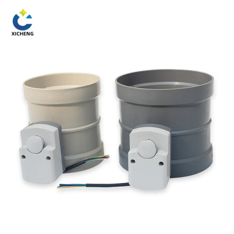
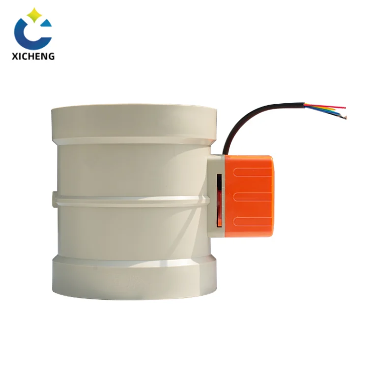
An electric motorized damper is a duct-flow control device built in two halves: a damper body whose blade swings across a round or rectangular duct, and an electric actuator bolted to the shaft that swings that blade on command. It is the powered cousin of the manual balance damper. Instead of a lever that a technician turns from a ladder, it carries a small motor that opens, closes, or holds the blade at an intermediate angle under the control of a thermostat, a ventilation timer, a zone panel, or a building automation system. Wherever a fan or an air handler needs a duct opened and shut, or held to a set airflow, without someone standing at the duct, the electric motorized damper is the standard device.
The damper has two basic personalities, and most specifications start by choosing between them. The first is the on-off, or two-position, damper: it opens fully or closes fully on a digital command. That is the form on a fresh-air intake that must seal off outdoor air the moment the air handler stops, and the form on a zone branch that a thermostat simply wants open or shut. The second is the modulating damper, which accepts an analog signal, usually 0-10 V or 2-10 V, and parks its blade at any angle in between so it throttles airflow continuously. That is the form an economizer uses to blend outdoor and return air in an exact proportion. Both are called electric motorized dampers; the difference is whether the controller sends a switch command or a position demand.
Where This Guide Sits in the Damper Family
The damper and valve family is larger than it first looks. Alongside the electric motorized damper sit the unpowered members for manual duty, the manual air valve and manual valve actuator, and the powered members this manufacturer builds: the electric valve survey of the whole family, the electric air valve guide that separates solenoid air valves from motorized duct dampers, the electric butterfly valve that uses a disc body, and the electric exhaust valve guide for the exhaust side of the network.
This guide takes the general-purpose electric motorized damper used for outdoor fresh air, supply air, and zone control: the category that carries a fresh-air intake through the wall into the return side of a unit, divides a central system’s output among rooms, and trims the airflow that reaches each space. It covers the mounting points where the damper earns its place, the fail positions that decide what happens on a power cut, the voltage and control signal options, round versus rectangular construction, materials, sizing, and the codes that make the powered damper mandatory on outdoor-air openings.
How an Electric Motorized Damper Fits the Damper and Valve Family
Knowing where a device sits inside its own family keeps a specification from drifting into the wrong catalog. The family has three layers: the duct dampers that swing a blade across a duct, the valves that close a bore inside pipe, and the life-safety dampers that protect a fire-rated partition. The electric motorized damper belongs in the first layer, and the fastest way to place it is to walk the layers quickly.
The Family: Control Dampers, Valves, and Life-Safety Dampers
The control damper layer holds everything that adjusts airflow in ductwork: the manual balance damper a technician sets on site, the motorized damper that adjusts itself on a signal, and the backdraft and pressure-relief dampers that move only when pressure calls them. That layer is surveyed from the whole-duct point of view in the plastic duct damper guide, which covers the full damper family for duct systems. The valve layer, by contrast, closes a bore in pipe and fluid systems; the powered part of that layer is covered by the electric valve family overview. The life-safety layer, fire and smoke dampers that snap shut on heat or smoke signals, is a separate product line entirely and is discussed later in the code section of this guide.
What This Guide Adds Beyond the Exhaust-Valve Guide
The closest relative to this page is the electric exhaust valve guide. That article follows the exhaust side of the network: the dampers that close fume ducts when a system idles, survive acid and solvent chemistry, and cut off automotive exhaust cutouts. This guide takes the supply and return side instead, where the air is ventilation air rather than exhaust fume: the fresh-air intake that brings outdoor air in, the supply duct that carries it to a space, and the zone branches that meter it room by room. The exhaust side and the supply side share the same motorized-damper mechanics, but the duty, the chemistry, and the fail positions differ, which is why the two guides sit side by side.
When a Solenoid Air Valve Is Not a Motorized Damper
One boundary deserves an explicit note because buyers search across it constantly. A solenoid air valve is a fast, two-position electric valve that snaps a small valve element open or shut in a fraction of a second, typically for pilot air, switching, and isolation on compressed-air circuits. An electric motorized damper is a larger, geared device that strokes its blade over tens of seconds and can hold intermediate positions. The distinction, the applications that suit each, and the moments where the two are confused are worked out in the electric air valve guide; here it is enough to say that a motorized damper controls duct airflow, not a pneumatic circuit.
The Main Duties: Fresh Air, Supply, and Zone Control
An electric motorized damper earns its place in a handful of standard positions, and the position dictates the specification more than anything else in the catalog. Four duties dominate: closing the outdoor-air intake when it is not wanted, dividing air among zones, supplying makeup air to exhausted spaces, and trimming the outdoor-air fraction in a mixed-air unit. Each is a different job for the same machine.
Outdoor-Air Intake Damper on the Return Side of the Air Handler
The single most common installation for this product is the fresh-air intake that brings outdoor ventilation air into the return side of an air handler or furnace. The outside-air duct is connected to the return of the central unit, and it must not be allowed to sit open at all times. A continuously open intake drags in unconditioned air whenever the fan runs, whether or not anyone needs it, wasting the energy spent conditioning the building and, in humid climates, pushing indoor humidity up. The building-science guidance from the U.S. Department of Energy’s Building America program states the rule plainly in its outdoor-air intake damper guide: install a motorized damper that can close the air intake, then let a timer or electronic control open it for the intervals the ventilation requirement demands and close it between intervals.
Why the Fresh-Air Damper Must Close When Not in Use
The reason the intake carries a damper at all is that ventilation is an allowance, not a continuous firehose. A home or a lightweight commercial space needs a set volume of fresh air per hour to meet code, but pulling that volume every minute of every day over-ventilates: it raises energy use, and in damp climates it lets outside humidity roll in on the supply stream. A motorized damper converts the fresh-air intake from an always-open hole into a valve that admits a measured amount and then seals. Alongside the energy and humidity argument sits the interlock argument: when the air handler or fan is off, an open intake is simply a free path from outside into the building envelope, and the damper closes that path with the same action.
Timer-Based Intermittent Ventilation and ASHRAE 62.2
In the residential and light-commercial form, the electric motorized damper on the fresh-air intake is run by a ventilation timer. The installing contractor sets the timer to open the damper in short, repeated intervals so that the total fresh air delivered over a day meets the ventilation minimum of the governing standard, commonly ASHRAE 62.2 for low-rise residential buildings. Products sold for exactly this duty describe themselves as 24-volt power-open, power-close fresh-air dampers, and manufacturers publish a sizing path for them: pick the damper for three times the continuous ventilation flow and let it run in a rough ten-minutes-on, thirty-minutes-off rhythm, then confirm the result against the standard’s calculation. The coordinating detail is balance: the timer can open the fresh-air damper in step with an exhaust fan so the house does not pressurize, which is why the fresh-air side and the exhaust side of the network are designed together.
Zone Branch Dampers: One Motorized Damper per Zone
The second great duty is zoning. A central air handler serves a whole building, but the rooms it serves do not all want the same climate. Zone control fits an electric motorized damper into the branch duct of each zone, so the single unit can heat the lower rooms in winter while letting heat rise to the upper floors, and cool the upper rooms in summer while the cooler air sinks. Each zone branch is opened or shut on the authority of that zone’s thermostat or its zone panel, and the result is that the system conditions only the rooms that are occupied and only when their temperature calls for it. That is the energy-efficiency story of the motorized damper at its simplest: heat or cool the rooms that need it, not all of them at once.
Zone Panel and Thermostat Cycling
In a residential system a zone panel or a communicating thermostat cycles each branch damper between open and closed as zone temperatures demand. The dampers themselves are most often round, fitting round branch duct, and come in the sizes that match those branches, typically from four to sixteen inches. Manufacturers of zone dampers rate the motor to hold the blade against duct static pressure, and lines such as the EWC Controls ND rectangular series carry a motor with roughly seventeen inch-pounds of torque so the blade stays where the zone panel left it against the air pushing on it.
Bypass Damper and Pressure Relief
Zoning creates a pressure problem that the damper layout has to answer. When every zone except one is satisfied and closed, the single open branch is asked to pass the whole fan flow, and the duct can build up pressure that strains the blower. The standard answer is a bypass damper that opens to bleed off the unused flow, or a pressure-relief damper that dumps excess pressure, protecting the equipment. On the fresh-air side the same logic appears as the makeup-air kit: a pressure-relief damper and vent hood that opens to admit replacement air when exhaust appliances, such as range hoods over a high-BTU cooktop, draw more air than the space can passively supply. The exhaust pairing and the duct-pressure work are the subject of the electric exhaust valve guide; here the point is that the motorized damper divides air, and a second family of relief dampers keeps the division safe.
Supply and Makeup Air for Exhausted Spaces
The third duty is supply and makeup air. A kitchen, a laboratory, or a dense process room exhausts a large volume of air, and that air has to come from somewhere. If the exhaust demand exceeds the air that infiltrates naturally, the space depressurizes, fans stall, and combustion appliances can back-draft, which is why the gas side of the same network carries its own shutoff in the manual gas valve guide. A motorized makeup damper opens in step with the exhaust fan to admit outdoor air through a dedicated makeup duct, keeping the space balanced. The steepest residential example is range-hood makeup: a large hood may move hundreds of cubic feet per minute, and a matching makeup-air damper system lets a home draw that volume without over-pressurizing or starving the space, with relief dampers protecting the path.
Economizer and Outdoor-Air-Fraction Control
The fourth duty is the commercial economizer. On a packaged unit or a building AHU, the controller decides how much of the supply stream is outdoor air and how much is return air, using outdoor-air dampers and return-air dampers that modulate in opposite senses. When the weather is mild, the economizer pulls mostly outdoor air and runs the compressor less, which is where the energy payback of the motorized damper is largest. The control signal is analog, the blades park at partial angles, and the outdoor-air damper at the unit intake is, in energy-code terms, the motorized shutoff damper that seals the unit when the building is unoccupied. The same powered damper therefore serves two masters: modulating outdoor-air fraction while the unit runs, and closing the opening when the unit stops.
Power-Open/Power-Close vs Spring Return: Fail-Safe Position
Every electric motorized damper has to answer the same question before it is installed: where should the blade go when the power goes away? The answer is called the fail-safe position, and it is set by the actuator design, not by the controller. Two families of actuator cover nearly every duty. A power-open, power-close actuator drives the blade in both directions and parks it wherever the last command left it when power is lost. A spring-return actuator holds the blade against a spring while powered and lets that spring drive it to one fixed position the moment power drops. Choosing between them is the first specification a buyer writes down, because it decides what happens in an outage before any control signal can act.
Power-Open, Power-Close Two-Position Dampers
The power-open, power-close damper is the workhorse of the catalog. The motor drives the blade open when it receives one signal and drives it shut when it receives another, and with both signals removed the blade simply stays where it is. Products built for residential fresh-air ventilation, such as the Field Controls FAD series sold as 24-volt power-open, power-close fresh-air dampers, work on exactly this scheme: they hold the open or closed position only while power is continuously applied, so the ventilation timer must energize the damper or close a contact to move it any distance. The trade-off is simplicity and low cost against a real gap: a two-position, non-spring-return damper loses its blade position in an outage, opening nobody and closing nobody on its own.
Spring Return, Fail-Closed: The Fresh-Air Default
Where the loss of power must produce a definite blade position, the specification moves to a spring-return actuator, and the single most common setting is fail-closed. A fresh-air intake that seals by spring when the building loses power keeps unconditioned outdoor air out and keeps the envelope tight when nothing is controlling the unit. Residential lines such as the manufacturer-rated Suncourt spring-return dampers and the EWC RSD series are sold as normally closed under power loss, and industrial two-position power-open, spring-close models—for example the JEDCO CD100A—are built the same way. On a fresh-air intake, fail-closed is the conservative default: the worst case of losing the damper is that ventilation simply does not run, not that the building is flooded with unconditioned air.
Spring Return, Fail-Open: Equipment-Cooling and Relief Duty
Fail-open is specified where loss of the damper must leave a path open rather than sealed. The clearest example is combustion or equipment cooling: a furnace or boiler room that vents through a damper needs that path open whenever the equipment could run, and an outage must not trap exhaust in the space. Relief and makeup duty points to the same choice—a pressure-relief damper or a makeup-air path that defaults open protects the space when the actuation power fails. The buying decision therefore depends on which failure the building tolerates better: a sealed path that starves ventilation, or an open path that leaks unconditioned air.
| Duty | No-power position | Typical actuator | Why |
|---|---|---|---|
| Fresh-air intake, return side | Closed | Spring-return fail-closed, or power-close with powered timer | Seals unconditioned air out when the unit is off |
| Zone branch damper | As last commanded (or open) | Power-open/power-close with spring assist in some zones | Holds position when the zone panel loses power |
| Economizer outdoor-air damper | Closed | Spring-return fail-closed shutoff damper | Metered outdoor-air fraction, sealed when empty |
| Makeup-air or relief path | Open | Spring-return fail-open | Combustion and exhaust safety keep the path clear |
| Equipment-cooling vent | Open | Spring-return fail-open | Overheating is prevented by leaving the vent clear |
Why Fail-Safe Position Matters in Humid Climates
The fail-safe choice stops being theoretical in a humid climate. A damper that defaults open on a fresh-air intake turns the duct into a chimney for humid outdoor air whenever the utility power flickers or the ventilating timer stops, and the air handler can pull that humidity into the supply stream on its next start. The Building America guidance that closes the intake when ventilation is not required applies with extra force here: the intake damper is fail-closed or power-closed, never left to drift. Specifying the fail position from the climate, rather than from habit, is what separates a damper that protects the house from a damper that merely happens to be installed.
Voltage, Wiring, and Control Signals
The brain that drives an electric motorized damper is whatever controller sends the command; the language it uses is the supply voltage and the control signal. Most motorized damper actuators accept one of two supply voltages and one of two control languages, and the choice locks in the wiring and the transformer at the same time.
24 VAC vs 120 V Supply
Low-voltage 24-volt actuation is the dominant choice for residential and light-commercial dampers. It runs the damper off a control transformer through small-gauge thermostat wire, keeps working power off the control circuits, and is the voltage found on the typical fresh-air damper and zone damper in a house. Line-voltage 120-volt actuation is specified when the damper sits on its own circuit, when a low-voltage transformer is not convenient, or when the job’s wiring and disconnect are already at line voltage. Lines such as the Suncourt dampers, the FAMCO ADC/ADO series, and the EWC iO outdoor-air damper are offered in both 24-volt and 120-volt versions, so the model is picked to match the voltage already present at the installation rather than the other way around.
On-Off Control from a Zone Panel or Thermostat
Two-position dampers take a switch command. The zone panel, thermostat, or ventilating timer either energizes the actuator to drive the blade open, de-energizes it to let the blade close, or reverses a contact to swing it shut, and the blade lands at one end or the other. This is the simplest possible control loop and the one used for the fresh-air timer and for the majority of zone branches. Because the command is a contact closure rather than a measured value, the same on-off damper body is sold with different actuators to match the controlling device, which is where a standard like the electric valve actuator guide becomes useful for sizing the motor.
End Switches and Damper-Position Feedback
An end switch is a small microswitch inside the actuator that closes when the blade reaches one end of its travel, and it is worth more than its size on a two-position damper. The building automation system uses it to prove that the fresh-air damper actually opened before the ventilation cycle starts, or to verify that the fire system’s damper actually seated. On modulating dampers the same information is sent continuously as a feedback signal, so the controller can compare the blade position it asked for with the position the actuator reports.
Modulating Control: 0-10 V and 2-10 V Position Signals
Modulating dampers speak analog. The controller sends a direct voltage-level signal, most commonly 0-10 V or 2-10 V, and the actuator parks its blade at the angle that matches the signal value: about 0 V to the fully closed position, about 10 V to fully open, and every voltage in between to a proportional blade angle. Some actuator families add a 4-20 mA current-signal version for industrial analog loops. This is the control language of the economizer, where the outdoor-air fraction must slide continuously rather than snap to two positions, and of central HVAC systems managed by a building automation system. The distinction between a modulating motorized duct damper and a fast two-position air valve is drawn in the electric air valve guide; here the point is that modulating control is a signal choice, not a product category—the same damper body accepts either an on-off actuator or a proportional actuator.
Belimo and Ecojay Drop-In Actuators
Many motorized dampers ship with a bare shaft and accept a standard quarter-turn actuator, and in the North American market the de-facto mounting standard is the Belimo footprint. Zone-damper suppliers sell rectangular dampers pre-equipped with actuators built on the Belimo interface—the ZoningSupply line, for example, mounts Ecojay-by-Belimo actuators on aluminum zone dampers so the drive is interchangeable with any unit using that pattern. Interchangeability protects the job: when a zone damper actuator wears out, a drop-in unit of the same interface replaces it without revising the brackets or the wiring.
Torque, Travel Time, and Duty Cycle
Three actuator ratings translate directly into damper performance. Torque, expressed in inch-pounds, is the force the motor can exert at the shaft and must exceed the force of the air pushing on the blade; an undersized motor stalls, and a zone damper cannot hold position against duct static pressure. Travel time is how long the blade takes to sweep from closed to open—roughly 15 seconds on a fast zone damper versus 60 to 90 seconds on a large or multi-blade assembly—and it determines how quickly a damper can respond to a demand change. Duty cycle is the fraction of time the motor may actually run without overheating; modulating economy service runs briefly and rests, while a damper that cycles constantly must be rated for the real usage.
Round vs Rectangular Motorized Dampers
The motorized damper catalog splits into two bodies, and the duct shape picks the body before any other consideration. Round dampers fit round branch and intake duct, swing a single blade across the bore, and are the small, inexpensive workhorses of fresh-air and zone duty. Rectangular dampers fit square and flat-oval duct, carry one or more blades across the opening, and are the form used for low-leakage shutoff and modulating service on larger openings. Each has its own construction details, and choosing wrong forces an adapter or a hack on site.
Round Single-Blade Motorized Dampers
The round electric motorized damper is a length of round duct with a single blade pivoted across its axis, like a butterfly inside a pipe. The blade swings from a motor bolted on the outside of the body, and because the whole opening is crossed by one tight-fitting plate, a round damper seals well for its cost. Round dampers follow the duct sizing conventions of branch and intake work and are manufactured in the sizes those ducts use, most commonly from four to sixteen inches of inside diameter. The EWC Controls URD and the Soler & Palau MD series are typical of the breed: round bodies, single blades, motor options from two-position to spring-return, and travel times around fifteen seconds at the small end of the range.
Slip-in and Retrofit Round Dampers
A specific subsection of the round catalog exists for adding a damper to duct that is already installed. Slip-in round dampers—the EWC SID type, for example—come as a body that slides into an existing round duct run and is clamped or set-screwed in place, avoiding the flanges and the cutting that a mounted assembly demands. Retrofit inserts are sized to run inside a slightly oversized section or to mount at the junction of two duct pieces. Contractors retrofit zone and fresh-air dampers this way when reworking an existing system, which is the fastest path to motorizing a duct that was originally twinned with a manual damper on a ladder.
Rectangular Multi-Blade Motorized Dampers
Rectangular dampers cover openings too wide or too tall for a single blade to seal or to move. Instead of one plate they carry several parallel blades—two, four, six, or more depending on the opening—linked to turn on a common axis, so the whole bank opens and closes as one unit. The blade pattern matters. Opposed-blade dampers turn adjoining blades in opposite directions, which spreads the airflow evenly across the opening and gives smoother proportioning in modulating service. Parallel-blade dampers turn all blades the same way, which is simpler and slightly tighter shutoff but aims the flow to one side as it opens. For shutoff and economizer work the multi-blade form is the standard, and for wide assemblies the manufacturer gangs sections on a jackshaft so one motor drives several damper sections together.
| Characteristic | Round single-blade | Rectangular multi-blade |
|---|---|---|
| Duct fit | Round branch and intake duct | Square and flat-oval duct, large openings |
| Blade arrangement | One blade across the bore | Two or more linked blades |
| Typical size range | 4 to 16 in diameter | 8×6 in up past 24×24 in |
| Leakage control | Good for its cost, single seal line | Best low-leakage class, multi-seal |
| Proportional modulating duty | Rare, usually two-position | Standard for economizer proportioning |
| Common applications | Fresh-air intake, zone branches | AHU shutoff, economizer, large zones |
Jackshafted Assemblies
Wide rectangular dampers pass the point where one blade bank can be reliably driven, and manufacturers begin jackshafting above a width of around thirty-two inches. A jackshaft is a long connecting bar that drives two or more parallel damper sections from a single actuator, keeping every blade in step without oversizing the motor. The linkage is delivered as part of the assembly; the installer bolts the sections together and the drive, and the field work is alignment rather than design.
Rectangular Zone Dampers with a Standard Actuator Interface
The rectangular form is also where the zone-damper market standardized its actuator mounting. Suppliers such as ZoningSupply build rectangular aluminum zone dampers in the common duct sizes from about 6×6 inches up to 24×24 inches, pre-fitted with a Belimo-pattern actuator so the drive can be swapped for any unit on the same interface. This is the shape of the dampers that one zoned air handler needs when the branches are rectangular, and it connects directly to the actuator interchangeability covered in the voltage and wiring section.
Selecting by Duct Shape and Branch Size
The selector is simple once the two bodies are clear: measure the duct, not the dampers. Round duct and small branches take round single-blade dampers; rectangular or large openings take rectangular multi-blade units, with jackshafting above roughly 32 inches of width and opposed blades where the damper must proportion rather than just close. Round dampers seal better per dollar in the small sizes; rectangular dampers own the low-leakage and modulating classes. When the opening is a fresh-air or zone branch, buy the round body that matches the duct size; when the opening is the intake of a packaged unit or an AHU, buy the rectangular low-leakage body.
Materials, Seals, and Leakage
The body material and the sealing system decide how well an electric motorized damper survives its duct and how tight a shutoff it can claim. Material is chosen from three realities: the air chemistry it will touch, the temperature range of the system, and the leakage class the job has to meet. Sealing is the engineering that turns a blade gap into a closed valve.
Galvanized, Stainless, and Aluminum Bodies
Sheet-metal dampers are built from three metals in the same shapes. Galvanized steel is the default: it is stiff, cheap, and fine for ordinary ventilation air, and it is what standard round and rectangular zones are stamped from, typically in the 26- to 28-gauge range. Stainless steel is specified where moisture, washdown, or a chemical trace would rust the galvanized product — coastal outdoor air, commercial kitchen exhaust, and process spaces are its home. Aluminum is chosen for weight and for corrosion resistance in damp or coastal duty, and its lower weight is why the better zone-damper lines use it for rectangular blades. A reputable manufacturer states the material for the body and blades separately in its catalog, because it is common for a damper to mix a galvanized body with stainless blades where the blades see the airflow.
Blade, Jamb, and Stop Seals: Foam, Rubber, Poron
Leakage happens where the blade meets its frame, and the sealing system closes those paths. Blade seals sit on the edges of each blade; jamb seals line the sides of the damper where the blades turn; stop seals run along the closed-face edges. The material is closed-cell foam for springy, long-lived compression, rubber for abrasion resistance, or a cellular urethane such as Poron where the manufacturer wants both. The Field Controls dampers, for example, use a closed-cell foam rated to survive the million-ish cycles of a fresh-air damper opening and closing without collapsing, and the EWC round dampers seal with Poron gasketing. Seals also define the leakage class: a damper with full blade, jamb, and stop seals plus adjustable compression earns the low-leakage rating that economizer and energy-code service demand, while a plain unsealed body seals only by blade-to-frame metal contact.
Thermally Broken and Insulated Dampers for Outdoor Air
A damper mounted on the exterior wall faces a temperature gradient the rest of the catalog does not. The cold outdoor side conducts heat through the metal blade and frame to the warm indoor side, wasting energy and condensing moisture on the frame. Thermally broken dampers interrupt that conduction with an insulating spacer between the inner and outer layers of the frame — the approach taken in the Ruskin thermally-efficient line that also builds the body in galvanized, stainless, or aluminum — and insulated dampers add a foam layer inside the blades for the same reason on the exposed face. Any outdoor-air intake wider than a token gap is worth the thermally broken body, because the damper is the largest single piece of metal bridging the building envelope at that point.
PP, PVC, and PPS Bodies for Corrosive Duty
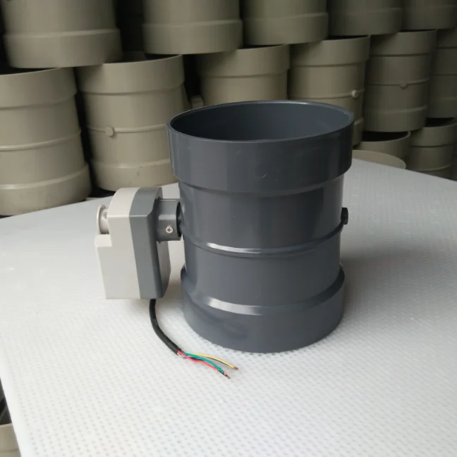
Air that would eat sheet metal gets a plastic body. The same damper mechanics carry over to injection-molded or fabricated polypropylene (PP), PVC, and polyphenylene sulfide (PPS) bodies that shrug off acid fumes, salt, and the solvents that attack galvanized steel, which is why corrosive-service supply and fresh-air lines on this site route through the PP duct damper product line. The plastic-form construction, including the one-piece molded bodies shown above, is covered in the site’s polypropylene sheet properties guide. Seals that the metal dampers take for granted become critical here, because a plastic blade must meet its frame with a full gasket to make up for a body that is lighter than steel. When the duct system itself is PP or PVC, the motorized damper should match it; a galvanized damper glued into a plastic duct is a corrosion cell waiting to start.
Sizing an Electric Motorized Damper
A damper is sized to the duty it serves, not to a formula in the catalog. The two jobs in this article — metering intermittent fresh air and opening a duct branch — each have their own sizing path, and both start from the airflow the duct actually carries.
Intermittent Fresh-Air Sizing: CFM x 3, Ten Minutes On, Thirty Off
Fresh-air dampers run in cycles rather than continuously, so the damper must be larger than the average ventilation flow to deliver the same volume in a shorter window. The rule manufacturers publish for a power-open, power-close fresh-air damper is to size it for three times the continuous ventilation flow: if the house needs 100 cubic feet per minute of fresh air on a continuous basis, the damper is sized near 300. The reason is the duty-cycle math. Run a damper roughly ten minutes on and thirty minutes off, as a typical ventilating timer does, and the interval flow is four times the continuous average — so the three-times sizing offers a little headroom, and the installer confirms the actual delivered volume against the ASHRAE 62.2 calculation for the dwelling. The timer is set so the total daily volume meets the standard, and the damper is sized to pass that interval flow without a severe pressure drop.
Match the Duct Opening; Undersize by 1/4 Inch
Mechanical fit comes next. The damper body is specified to match the mating duct, and the common field convention is to build rectangular dampers a quarter-inch smaller than the opening they mount in, so the assembly slips in and the sealant and fasteners carry the joint rather than a forced fit. Round dampers are bought to the duct’s inside diameter and clamp to the cut ends. On retrofit work the actual opening is measured before measuring from a plan, because decades of field revisions make the as-built duct the only reliable number. Sizing to the opening, not to the nominal size stamped on the duct, is the rule that prevents the adapter fitting that appears on every retrofit job.
Velocity, Pressure Drop, and Actuator Torque
Two performance bounds close the sizing loop. Velocity — air speed through the open damper — sets noise and erosion; a damper that is too small for the flow produces high velocity, whistling, and blade wear, so the damper is upsized where the duct speed is high. Pressure drop across the open damper is the resistance the system fan has to overcome; every damper adds some, and the sum of all dampers in a supply system must fit inside the fan’s available static pressure. On the drive side, the actuator torque must exceed the moment the airflow pushes on the blade at the damper’s maximum differential pressure, plus the seal friction at the closed position.
That is the point where the rectangular zone dampers with their stronger motors enter the picture: the blade must not be blown open or held half-open against the air pushing on it. Classifying a damper for 500 or 1,000 feet per minute is common in catalog data, and the selection keeps both the velocity and the pressure drop inside what the system can afford.
Code and Compliance
Parts of the motorized damper catalog are optional hardware, but the damper on an outdoor-air opening is sometimes a code requirement, and the code language tells a buyer exactly which duty is non-negotiable. Two standards drive most residential and commercial specifications: ASHRAE 62.2 for ventilation in low-rise residential buildings, and the commercial energy-efficiency provisions built into the International Energy Conservation Code, whose outdoor- and exhaust-air damper clause is the one that makes a motorized damper mandatory on larger equipment.
ASHRAE 62.2: Timer-Controlled Residential Ventilation
ASHRAE 62.2 is the ventilation standard for low-rise residential buildings, and it is the calculation behind the intermittency already covered in the fresh-air section. The standard sets a minimum ventilation rate for a dwelling based on floor area and number of bedrooms, and it explicitly allows that minimum to be served by an intermittent ventilation system — a damper, a timer, and a fan — as long as the delivered volume, averaged over the run cycle, meets the requirement. That permission is what gives the timer-based fresh-air damper its legal footing: the sizing-multiplier rule exists because 62.2 interpolates the intermittent volume to a continuous-equivalent rate. The installing contractor’s job is to pick the damper and timer so the daily delivered fresh air passes the 62.2 number for the specific dwelling, and to record that the configuration meets it.
IECC C403.2.4.4: Motorized Dampers on Outdoor- and Exhaust-Air Openings
The commercial side is much more explicit. The International Energy Conservation Code’s mechanical provisions include a clause on outdoor-air and exhaust openings — the section numbered C403.2.4.4 — which requires motorized dampers on outdoor-air intakes and exhaust openings for larger HVAC equipment, sized to the requirements of the building, and closed when the equipment is off. The full text of C403.2.4.4, including the exception for openings whose design is such that no damper fits, is on the public code site as part of the commercial energy-efficiency chapter.
For the purposes of this guide, the clause is the reason the motorized shutoff damper appears on packaged rooftop units and building AHUs at all: the unit intake and the exhaust louver both carry a powered damper that closes when the unit stops, tying back to the fresh-air duty and the fail-closed position covered in the fail-safe section. The exhaust-side companion to the clause — dampers on fume ducts and commercial kitchen exhausts — is the subject of the electric exhaust valve guide; here, the same code clause is read from the supply and outdoor-air side.
Control Dampers Are Not Fire or Smoke Dampers
One distinction protects the entire specification: an electric motorized damper that closes on a control signal is not a fire or smoke damper, even when it sits in the same sized opening. A control damper is a flow-management device, and it is not rated to close automatically on a fire or smoke detection signal, nor does it carry the hourly fire-resistance rating of a listed fire damper. Fire and smoke dampers are separately listed, separately tested products that close on heat or smoke signals and hold a rated integrity.
The class of building that requires one on every duct penetration is determined by the fire code — and where a duct passes a rated wall or floor, the penetration is protected by a listed fire damper, with the motorized control damper in series or in a different duct, not substituting for it. This is the point at which buyers must look up the actual requirement before buying, because a cheap control damper in a fire-rated opening is a code violation that appears at inspection. The Wikipedia entry on flow dampers makes the same separation between the control/flow device and the life-safety device that the catalogs draw.
Installation and Maintenance
An electric motorized damper that is specified well but installed carelessly still fails in the field, usually in the first winter. The installation rules are short and mechanical, and they prevent the bulk of the service calls: orient the blades properly, mount the motor where it can be reached, feed the actuator with a transformer it does not starve, and calibrate the travel before trusting the end switch.
Mounting Rules: Blades, Linkage, and Height
The blade orientation is the first rule, and it sounds odd until it is explained. In a round damper or on the blade rows of a rectangular damper, a horizontal blade is preferred for shutoff service because it lets gravity and the seal work together and because a vertical blade can sag under its own weight over years. Many catalogs print it as a rule: install with the blades horizontal, and in a round duct this means the axis of rotation is horizontal.
When the damper body has a linkage side — the side where the blades are joined to the drive — that side faces the direction prescribed in the installation sheet, and the motor is mounted on the accessible height or service side, not buried against a wall or above a finished ceiling. Wide jackshafted assemblies are aligned section by section before the drive is connected, and the shaft is centered in its end bearing. If the damper shares ductwork with a manually set unit, the manual air-balancing damper handles the trim; the motorized damper is not asked to do both jobs.
Wiring, Transformer Sizing, and Travel Calibration
On the electrical side, the transformer is the first thing to get right. Several spring-return actuators across a system can draw more inrush than the little control transformer that powers one thermostat, so the transformer is sized for the sum of the actuator ratings, and 24-volt wiring is run in the gauge the manufacturer specifies for the distance. Polarity and the common wire matter on the ventilating timer, because both switch legs remove power for the damper. On two-position dampers the travel is calibrated so the blade lands fully shut without grinding the stop, and on modulating dampers the 0-10 V or 2-10 V signal range is set so the fully-open and fully-closed endpoints match the actuator’s mechanical stops. End switches are adjusted after travel calibration, not before, because a switch that trips three degrees early shuts off the ventilation cycle that the building automation system is trying to prove.
Seasonal Checks and Manual Override
Maintenance on a motorized damper is modest but not zero. In spring and autumn, when the fresh-air damper and the zone branches have been idle for a season, the standard check is to cycle each damper end to end once, confirm the end switch still proves the open state, and listen for a blade that is binding on its seal. Outdoor-air dampers get a second glance for birds and debris at the intake screen. The manual override is the operating fallback: most actuators carry a release lever or a hand crank so an operator can open or close the damper by hand when the controller is being serviced or the power is down for half a day.
Systems with bleed and purge fittings upstream use the same manual logic as the piping covered in the manual bleed valve guide — drain the section before touching the drive, and never force a seized blade through the motor. A damper that will not move when cycled is usually a seal that has glued itself to the blade after a season of sitting closed, and the fix is to release the override, free the blade by hand, and let the seals relax.
How to Choose: Selection Checklist
All the choices in this guide collapse into one ordered pass. The eight steps below walk from the mechanical form out to the material, and answering them in order produces a complete damper specification without rework. Keep the answer to each line short; the sum is the datasheet.
- Duct form. Round duct and small branches take a round single-blade electric motorized damper; rectangular openings and large intakes take a rectangular multi-blade unit, jackshafted above roughly 32 inches of width.
- Size. Match the actual opening to the empty side of the damper — round bodies to the duct’s inside diameter, rectangular bodies a quarter-inch under the opening for slip-in fits, and for fresh-air duty size for about three times the continuous ventilation flow.
- Voltage. Pick 24 VAC for control-transformer wiring in houses and light commercial, 120 V where the damper sits on its own line-voltage circuit. Match the version that exists on site rather than adding a voltage where none is convenient.
- Fail-safe position. Choose fail-closed for outdoor-air intakes that must seal when power dies, fail-open for makeup and equipment-cooling paths that must stay clear, and power-open/power-close for zone duty where holding the last position is acceptable.
- Actuator rating. Confirm torque exceeds the moment of the airflow at the damper’s maximum differential pressure, and confirm the duty cycle suits the cycling rate — the zone damper that cycles all day is not the same motor as the fresh-air damper that runs ten minutes an hour.
- Control signal. On-off for a zone panel, thermostat, or ventilating timer; 0-10 V or 2-10 V modulating with a feedback signal if the damper must proportion, as the economizer does.
- Leakage class. Demand blade, jamb, and stop seals with adjustable compression for low-leakage shutoff and economizer service; plain single-blade round dampers for ordinary branch duty where a modest leakage is acceptable.
- Material. Galvanized for clean interior air, stainless or aluminum for moisture and coastal duty, thermally broken for outdoor-air framing, and PP, PVC, or PPS for corrosive supply lines where the duct system itself is plastic.
Budget-to-Grade Placement in the Cluster
Once the specification is written, it lands in a catalog tier. The general-purpose electric valve family here is surveyed in the electric valves product page, which covers the full powered-valve and damper range for ordering; the duct-side plastic bodies are sold through the PP duct damper line; and the fast two-position solenoid-air-valve alternative, where the job calls for a snap action on compressed air rather than a stroking duct damper, sits on the electric air valve page. The checklist determines which of these catalogs the part actually belongs to, and the budget placement follows the duty: a cheap round on-off damper for a fresh-air branch is not the same part as the low-leakage rectangular modulating unit an economizer calls for, and buying the part the duty demands is cheaper than buying the part the catalog sale highlights.
Electric Motorized Damper FAQ
Do I need a motorized damper on my fresh-air intake?
If the intake connects to an air handler or furnace return and serves a code-governed dwelling or space, yes — the ventilation air has to be metered, and a continuously open intake over-ventilates and drags in unconditioned air whenever the fan runs. An electric motorized damper closed by a timer between ventilation intervals is the standard device: the Building America guidance recommends exactly this, and IECC C403.2.4.4 requires motorized dampers on outdoor-air openings of commercial equipment. On a small home duct where a damper already exists with a manual lever, a manual balancing damper may cover the job; on any intake that must open and seal by itself, the motorized form is the right call.
Normally open or normally closed for my application?
Base the fail position on the duty, not on habit. A fresh-air intake that must seal unconditioned air out when power fails is normally closed, which is also the humidity-safe default covered in the fail-safe section. A makeup-air or equipment-cooling path that must stay clear during an outage is normally open, because sealing it would starve combustion or trap exhaust. Zone branches usually hold their last position with a power-open/power-close actuator, and only zones where a defined no-power state is required add a spring return.
24 VAC vs 120 V motorized damper: which do you choose?
Match the voltage that already exists at the installation. 24 VAC runs off a control transformer through thermostat wire and dominates residential and light-commercial zones and fresh-air dampers, so it is what control panels and timers expect. 120 V is chosen where the damper sits on its own line-voltage circuit, where no low-voltage transformer is practical, or where the disconnect and wiring are already at line voltage. Since most manufacturers sell the same damper body in both versions, the decision is made from the site wiring rather than from the catalog.
What does 0-10 V modulating control do?
It turns the damper into a proportional device. The controller sends a direct voltage between about 0 and 10 volts, and the actuator parks its blade at the matching angle — near 0 V for closed, near 10 V for open, and every voltage in between to a corresponding position. That is the signal an economizer uses to blend outdoor and return air in an exact proportion, and it is the difference between a damper that throttles airflow continuously and an on-off unit that only snaps to two positions.
Can a motorized damper replace a manual balancing damper?
Not for the balancing job itself. A manual balance damper is set once by a technician to the fixed flow a branch needs and then left alone; a motorized damper is an active device that changes position on signal. The two serve different roles — the motorized damper opens, closes, or throttles on command, while the manual damper holds its hand-set trim. On a zone branch the manual unit is generally removed and the motorized damper takes the whole duty; on a fixed-balance system the manual damper stays and no motor is added. The manual alternatives are covered in the manual air valve guide if the job really is fixed-flow.
Are motorized dampers available in PP or PVC for corrosive fumes?
Yes. The same damper mechanics are built into injection-molded or fabricated polypropylene, PVC, and PPS bodies that stand up to acid, alkali, and solvent-laden air where galvanized steel would corrode, which is the domain of the site’s PP duct damper line and the polypropylene sheet properties guide. Plastic bodies rely on full blade, jamb, and stop seals to make up for being lighter than steel. If the duty is exhaust rather than supply — fume ducts, scrubbers, automotive cutouts — the corrosive-service companion is the electric exhaust valve guide.
Key Takeaways
An electric motorized damper is a damper body plus an electric actuator: either a two-position damper that opens and closes on a switch command, or a modulating damper that parks its blade at any angle on a 0-10 V position signal. The controller decides which personality the spec carries.
Four duties dominate the catalog, and the installation decides the spec: closing the outdoor-air intake when it is not wanted, dividing air among zone branches, supplying makeup air to exhausted spaces, and trimming the outdoor-air fraction of an economizer.
Choose the fail-safe position from the duty, not from habit: fail-closed on outdoor-air intakes and economizer shutoff, fail-open on makeup and equipment-cooling paths, and power-open/power-close where holding the last position is acceptable.
Round single-blade dampers fit round branch and intake duct from about 4 to 16 inches; rectangular multi-blade dampers cover large and rectangular openings with the lowest leakage, opposed-blade proportioning, and jackshafted sections beyond roughly 32 inches.
24 VAC is the control-transformer standard on residential and light-commercial dampers; 120 V serves line-voltage jobs; 0-10 V modulating control is the BMS language of economizer air-fraction trim.
Galvanized, stainless, and aluminum cover ordinary and coastal air; thermally broken bodies are worth the cost on outdoor intakes; PP, PVC, and PPS bodies take over wherever the supply or fresh-air line carries corrosive chemistry.
The electric motorized damper is the control point of a building’s supply and fresh-air network: it meters outdoor air into the return side of a unit, cycles the zone branches that divide a system’s output, opens makeup air for exhausted spaces, and trims the outdoor-air fraction of an economizer, all on a thermostat, timer, zone panel, or building automation signal. Specify the duty first — fresh air, zoning, supply, or economizer — then pick the fail position, voltage, control signal, round or rectangular body, leakage class, and material, and the damper specification writes itself. The powered range of the family is the electric valves line, the motorized supply- and fresh-air product is the electric air valve page, and the engineering desk at contact us handles torque, leakage class, and CAD layout for specific duct networks.
