
An electric butterfly valve is a quarter-turn butterfly valve with an electric actuator bolted on top: a motor turns a circular disc through 90 degrees to open, close, or throttle the line, so the valve answers a switch, a 4–20 mA signal, or a program instead of a hand on a handle. On this site the electric butterfly valve sits inside the electric valve family covered by the electric valve guide, it is powered by the actuator the electric valve actuator guide explains, and it mounts on the same duct system as the plastic duct damper, with the manual air valve guide standing in as the unpowered counterpart.
This guide covers what an electric butterfly valve is, how the motor, gear train, stem, and disc drive the quarter turn, the butterfly types by body, seat, and connection, how an electric butterfly valve compares with a pneumatic one, when to specify on/off and when to specify modulating control, how to size torque and actuator, where electric butterfly valves are applied, and how to install, maintain, and fail-safe them. The focus here is the butterfly itself: the disc in the flow, the seat against it, and the quarter turn that is the heart of the valve. The motor, gearbox, and control details that bolt on top of that body are covered in the electric valve actuator guide, so this page stays on the valve.
What Is an Electric Butterfly Valve?
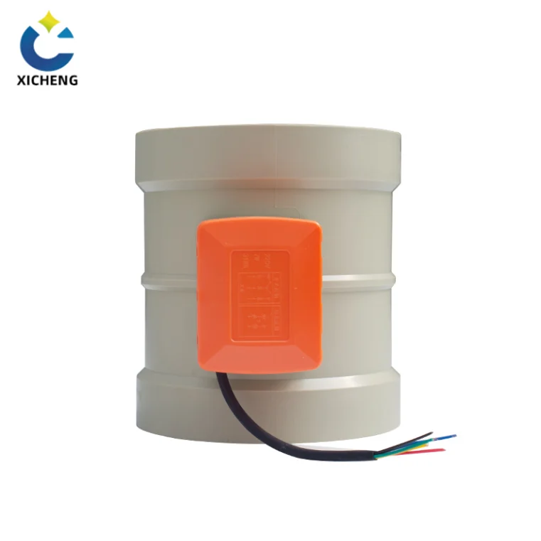
An electric butterfly valve combines two parts: a butterfly valve body and an electric actuator. The body is built from three components — a circular disc, a stem, and a seat — and the actuator bolts to the valve top and turns the stem. Because the closing mechanism is a disc that rotates, the butterfly belongs to the quarter-turn family of valves, the same family as the ball valve, but with a lighter, thinner body and a disc that stays in the flow passage even when fully open. That standing disc creates a pressure drop in the fully open position that a ball valve does not have, which is a central truth about the electric butterfly valve and the first fact to understand before selecting one.
A Quarter-Turn Valve with an Electric Head
In the closed position the disc is turned so it blocks the bore completely; in the open position it has rotated a quarter turn to sit edge-on to the flow, allowing nearly unrestricted passage. Rotating the actuator turns the disc either parallel or perpendicular to the flow. The butterfly valve is a large category of electric valve: an electric actuator closes and opens it, and the same assembly can serve as a blocking valve, a regulating valve, or, with the right seat, a check function in a pipeline. Electric actuated valves in general cover ball, plug, and butterfly bodies — the butterfly is the lightest and least expensive family among them, which is why so many automated water and air lines use it.
Why the Butterfly Suits Electric Actuation
The butterfly’s 90-degree stroke is a natural fit for an electric head. A compact motor and gear train can turn a thin disc through that quarter turn in a few seconds, and the disc generates comparatively low torque demand, so the actuator stays small and economical. The body also saves space and weight: butterfly valves occupy roughly 70 percent less face-to-face space than a flanged ball valve of the same diameter, which cuts pipe-support cost on large lines. The butterfly valve has been in use since the late 18th century in fabricated form, and a 1969 improvement by James E. Hemphill reduced the hydrodynamic torque needed to change the valve’s output, making the body still easier to drive by power. The engineering background of the quarter-turn disc is covered in the butterfly valve reference.
How an Electric Butterfly Valve Works
An electric butterfly valve converts electrical energy into mechanical torque through an electric motor and a gear train, and that torque rotates the valve stem. The control system sends a command — a contact closure, a 24 V signal, a 4–20 mA position value, or a fieldbus word — and the actuator turns the command into movement of the disc. Working power for the actuator is commonly AC 220 V or AC 380 V, with direct-current and 24 V variants on smaller valves, and the input signals are weak electrical signals such as 4–20 mA or 0–10 V. The mechanism is straightforward: the stem is driven by the electric device, and that makes the butterfly plate rotate 90 degrees to open or close the valve.
From Electrical Signal to Disc Rotation
Motor and gear train
The electric motor spins fast, and the gear train reduces that speed into the higher torque the disc needs to seat and to break free. In this sense an electric motor operated valve is the same mechanism whether the body is a ball, a butterfly, or a gate: the motor is the work source and the gears are the amplifier. Most electric rotary actuators use a reversing motor that travels in both directions, so the same unit opens and closes by swapping its rotation instead of gearing in a second motor. Where a plant already understands a motor-operated unit, the electric valve actuator guide carries the component-level detail of the motor, gear train, and worm drive.
Stem and disc: the 90-degree quarter turn
A circular disc sits in the center of the pipe, and the stem connects that disc to the actuator mounted on top of the valve. When the actuator rotates the stem 90 degrees, the disc turns from fully closed — its plane perpendicular to the flow, blocking the bore — to fully open, its plane aligned with the flow and offering nearly unrestricted passage. At intermediate angles the disc acts as a throttling element, reducing flow area smoothly. Two manufacturing families define the seat: resilient-seated, using an elastomer such as EPDM, NBR, or PTFE for bubble-tight shutoff, and metal-seated in high-performance or triple-offset designs for elevated temperatures and abrasive media.
Limit switches and position feedback
Internal limit switches stop the motor when the actuator reaches the fully open or fully closed position, protecting the gears from being driven past the end of travel. The switches are activated by cams mounted on the stem drive shaft, and the cams can be adjusted to fine-tune exactly where the valve stops in the open and closed positions. To check the state of a switch on a distant valve is not practical, so the regulating type carries feedback signals, and position feedback can be added on switch-type units to report the disc state back to the control system. A position transmitter on a modulating unit feeds back the actual position, and modern intelligent actuators log torque profiles during every stroke.
Manual override
Because an electric butterfly valve is a power valve, most units include a manual override so the disc can still be worked if the actuator fails. Many electric butterfly valves are supplied with a manual control assembly: when the actuator has a problem, the valve is opened and closed by the manual device without affecting the working conditions of the line. A handwheel or lever override is also used at commissioning to align the disc, and it stays available for emergencies. The concept of an actuator as a power-transmitting device is explained in the actuator reference, and the way actuators mount to valve stems is covered in the valve actuator reference.
Butterfly Valve Types by Body, Seat, and Connection
Electric actuated butterfly valves are not one product. The body style, the connection, the seat, and the sealing geometry all change where the valve works and how it is installed, and choosing the right combination determines installation cost, maintenance access, and long-term shutoff. The table below summarizes the common variants and where each fits.
| Type | Connection | Typical seat | Common use |
|---|---|---|---|
| Wafer | Flangeless, clamped between flanges | Resilient (EPDM, NBR) | Water, general HVAC |
| Lug | Threaded inserts for flange bolts | Resilient or PTFE | Dead-end service, frequent maintenance |
| Flanged | Full flange with bolt holes | Resilient, PTFE, metal | High pressure, larger diameters |
| Triple offset | Wafer, lug, or flanged | Metal laminate | High temperature, cryogenic, zero leakage |
| High performance | Typically flanged | PTFE or reinforced PTFE | Chemicals, steam, high-cycle |
| Sanitary clamp | Tri-clamp ends | EPDM, PTFE | Food, beverage, pharmaceutical |
| Fluorine lined | Flanged | PFA or PTFE lining | Severe corrosive chemicals |
Concentric vs. Eccentric Designs
Concentric (zero-offset) butterfly valves place the stem on the center line of the disc and rely on the flexibility of a resilient rubber seat for sealing. They are the most common and least expensive type, suited to low-pressure clean services, but the disc rubs the seat through the whole turn, which wears the rubber faster with frequent cycling. Double- and triple-offset designs offset the stem from the center line to reduce or eliminate that rubbing. Because of these differences, the torque curve and the sealing behaviour of an electric butterfly valve vary with the design, and actuator sizing should use torque data for the specific valve design and size rather than a generic catalogue figure.
Double-offset (high performance) butterfly valves
Double-offset butterfly valves are offset from the center line of the disc seat and body seal, and again from the center line of the bore. The offset creates a cam action during operation that lifts the seat out of the seal, so there is less friction than in the zero-offset design and less wear over time. High-performance units with reinforced PTFE seats handle media above 200 degrees C without the seat swelling, which is why they appear on steam and thermal-oil lines where a standard resilient seat would fail.
Triple-offset butterfly valves
Triple-offset valves add a third axis so that the disc seat contact axis is offset, virtually eliminating sliding contact between disc and seat. The seat is metal, machined to achieve a bubble-tight shutoff in contact with the disc, and the conical sealing geometry removes continuous seat contact during travel. Triple-offset electric butterfly valves suit high temperature and cryogenic service, and their long cycle life — measured in hundreds of thousands of operations — is why refining and zero-leakage isolation lines adopt them. Where the process demands zero visible leakage, a PTFE-seated or triple-offset design is chosen instead of a standard resilient seat rated only for Class VI shutoff per ANSI/FCI 70-2.
Connection Styles: Wafer, Lug, and Flanged
Wafer style is the most installed electric butterfly valve because it minimizes weight and cost: the valve sits clamped between two pipe flanges, held by the flange bolts. A wafer valve seals against a bidirectional pressure differential to prevent backflow, but it only has a small flow-control range, its pressure drop can be greater, and the design is prone to clogging where debris is present — points to weigh when the service is not clean water.
Lug style has threaded inserts on both sides of the body so it mounts with two sets of bolts and no nuts, which lets either side of the piping system be disconnected without disturbing the other. A lug valve in dead-end service is the safest pick, and engineers should note its pressure rating drops: a lug valve rated 1,000 kPa between two flanges drops to about 520 kPa in a one-flange dead-end arrangement. Flanged valves carry a full bolt circle and suit higher pressures and larger diameters, following pressure classes such as ASME B16.34, and they are chosen where wafer bodies would need impractical flange support.
Sanitary, Fluorine-Lined, and Specialty Variants
For food, beverage, and pharmaceutical duty, a sanitary clamp electric butterfly valve with tri-clamp ends and EPDM or PTFE seats provides crevice-free sealing and quick disassembly for clean-in-place systems. For aggressive corrosives, a fluorine-lined flanged valve with a PFA or PTFE lining protects the body from severe chemicals. On a corrosion-resistant duct system the same quarter-turn body appears as a motorized plastic disc valve, which the plastic duct damper guide and the electric air valve family on this site cover in detail.
Electric vs. Pneumatic Butterfly Valves
At specification time the most common question is whether an electric butterfly valve or a pneumatic butterfly valve fits the line. Both drive the same 90-degree disc; the difference is the energy and the fail behaviour. Pneumatic butterflies are driven by compressed air from a compressor; electric butterflies are driven by an electric motor and need only a power cable. The properties of the two are compared after a short look at each side.
The Pneumatic Butterfly Valve at a Glance
A pneumatic butterfly valve is a butterfly valve body with a pneumatic actuator: compressed air enters the actuator and rotates the disc through 90 degrees, so 0 degrees is fully closed and 90 degrees is fully open. For regulation, a positioner receives a signal and adjusts the disc anywhere in that 0-to-90 range, turning the switch valve into a regulating butterfly valve, and filter pressure reducing valves and solenoid valves are added to improve air control. The strength of the pneumatic side is speed and force from a compact package plus a spring return: a spring-return pneumatic actuator parks in a defined fail position when air is lost. The cost story is the supply — a compressor, air tubing, solenoid wiring, maintenance, and the electricity to run a compressor all add up, so pneumatic butterflies are most economical where a compressor already exists with spare capacity.
Why an Electric Butterfly Valve Wins on Many Lines
An electric butterfly valve runs on a power cable alone. It draws no supply gas, produces no emissions at the valve, and automates directly from the same 0–10 V, 4–20 mA, or fieldbus signals a control system already generates, where a pneumatic valve needs an extra I/P converter plus a positioner to translate an electrical command into air movement. When power disappears, a standard electric butterfly valve holds its last position because the internal worm gearing self-locks; a pneumatic spring returns to its fail position without extra hardware. The duct-side sister of that self-locking disc, an electric air valve, carries the same gear lock into a blade that throttles air in a ventilation duct. Electric units are the normal choice where no instrument-air network exists — the common case on plastic duct and fume plants — and their limitation is speed and duty cycle rather than air supply. On an exhaust fume duct the same no-air-network logic meets a code-required shutoff duty, which the electric exhaust valve guide treats for fan-interlocked service.
| Factor | Electric butterfly valve | Pneumatic butterfly valve |
|---|---|---|
| Drive | Electric motor and gear train | Compressed air and positioner |
| Power source | Power cable only; draws when moving | Compressor, tubing, solenoid plus wiring |
| Position on loss | Self-locking gears hold last position | Spring return gives a fail position for free |
| Position control | Direct 0–10 V, 4–20 mA, Modbus, Profibus | 4–20 mA via I/P converter and positioner |
| Speed | Seconds per stroke; torque at slower speed | Fast; speed adjustable with air throttling |
| Duty | S2/S4 duty with thermal motor protection | Continuous, but compressor and air cost |
| Emissions | Zero at the valve | Indirect; compressor energy and purge air |
| Infrastructure | Cable tray and terminal | Compressor room and air piping |
Which Fits Duct and Fume Plants
On plastic duct and fume extraction systems the electric butterfly valve is usually the better fit, because those plants typically have no compressed-air network and do not want one. Fume being moved is often corrosive enough that a compressor and air lines are an extra maintenance burden, while a small motor head simply takes a 24 V or 220 V feed. Where a take-off must only be open or closed without automation, the manual air valve and manual valve actuator guides show the unpowered counterpart, and the actuator comparison in the electric valve actuator guide extends this table to every quarter-turn and multi-turn body. Where a duct low point must be vented before a damper opens — or drained of condensate — the manual bleed valve guide shows that companion vent.
On/Off vs. Modulating Electric Butterfly Valves
An electric butterfly valve is ordered as one of two control characters: switch type or regulation type. The switch-type electric butterfly valve simply plays the role of opening and closing, running from limit switch to limit switch, while the regulation type receives a continuously varying signal and positions the disc to modulate flow, temperature, or pressure. The choice is independent of the valve body and is made on the actuator and its control board, and it decides whether the assembly can throttle the line or only isolate it.
The Throttling Control Window
A regulating electric butterfly valve throttles within a defined disc-angle window. A valve operating between 20 and 70 degrees open provides the best controllability; below about 30 degrees the high velocity around the disc breeds cavitation that can damage the seat and the disc, and much below that the flow becomes nearly zero with little change per degree. Above roughly 70 degrees the flow curve flattens and small angle changes no longer control flow effectively, so the valve loses control authority near wide open. For continuous throttling duty many users step up to an eccentric high-performance or triple-offset body, whose seat geometry handles the wear that repeated mid-stroke positioning causes, rather than a concentric resilient seat that sees the disc rubbing through the whole travel. On fuel-gas lines the same ranking holds — a butterfly is a throttling valve, not a shutoff valve, and the manual gas valve guide explains where a positive shutoff must sit upstream.
Control Signals and Positioners
Modulating electric butterfly valves take a setpoint from the control system and drive the disc to match. Working signals are 4–20 mA, 0–10 V, and fieldbus protocols such as Modbus RTU or Profibus; the positioner on the actuator converts the signal into precise disc travel while a position transmitter feeds the actual position back. On a modulating actuator the drive to the disc must be free of backlash, because even a few degrees of lost motion become visible flow instability on a throttling valve, and modern actuators combine high-resolution encoders with adaptive control algorithms that compensate for gear wear and reduce overshoot. The regulating type generates its own feedback signals, so the control room sees where every butterfly sits. The general engineering of a control valve and its positioner is covered by the control valve reference.
An Approximately Equal-Percentage Flow Characteristic
A butterfly disc produces an approximately equal-percentage flow characteristic rather than a linear one: beginning from a small opening, equal changes in disc angle give nearly proportional changes in the percentage of flow, which at large openings become increasingly large. For a line that must balance flows continuously — a scrubbing line tracking fan speed, a local exhaust hood holding face velocity as an operator moves, or a treatment train isolating one bed while others run — the modulating electric butterfly valve is the element that does the balancing. Where an on/off isolation is all the line needs, the same valve body with a switch-type head and limit switches is simpler and less costly.
Torque and Actuator Sizing for Electric Butterfly Valves
Correct actuator sizing is one of the most common risk points in butterfly valve applications. Undersizing leaves a valve that fails to open after shutdown, stalls part-way through the stroke, or loses shutoff under pressure; oversizing adds cost, stresses the shaft and gearbox, and can create control and seating problems. Proper sizing of an electric butterfly valve is not a matter of picking a torque number bigger than the valve: the chosen actuator must overcome the breakaway torque at the worst credible conditions, provide running torque through the full 0–90 degree stroke, deliver seating torque at the required differential pressure, and keep a margin for uncertainty and degradation. This section follows that discipline, which applies equally to the actuator component covered in the electric valve actuator guide.
Breakaway, Running, and Seating Torque
For a butterfly valve, torque demand is not constant across the stroke. It typically peaks at the closed position, where breakaway and final seating both occur, and sometimes near mid-stroke depending on disc profile, seat type, and pressure distribution. Breakaway torque is the torque required to start moving the valve from fully closed, and in many services it is the maximum torque the actuator will ever see. Several factors drive it — seat contact stress, static friction after the valve has been closed and dwelled, process pressure acting on the disc, temperature effects, and deposits or sticking from the medium. A valve that stays closed for a long period can develop a breakaway torque significantly higher than the torque measured during shop testing, which is why sizing on the worst-case breakaway torque under defined conditions, not on a nominal catalogue figure, is the first rule.
Safety Factors in Practice
A safety factor is a structured allowance for uncertainty — manufacturing tolerances, changes in friction over time, process deviations, aging, wear, and contamination — applied to the maximum required torque, often the breakaway or peak running torque. The commonly published guidance for electric butterfly valves is that output torque should be at least 1.2 to 1.5 times the maximum operating torque of the valve, and at least 20 percent above the valve’s maximum turning torque, while the selection guides for dirty, scaling, or viscous media call for a minimum 1.5-times multiplier on worst-case breakaway torque compared against the actuator’s peak torque curve. The same sources warn against the blind multiplier: applying an arbitrary large factor without a realistic base torque can oversize the actuator and transfer excessive load into the shaft, disc, seat, or gearbox. The valve and actuator should be treated as one system, never as independent parts.
Size, Differential Pressure, and Line Velocity
Matching the valve’s nominal diameter to the pipe is the largest single selection error; Cv, pressure drop, velocity limits, and actuator torque must all align. For liquids, line velocity should stay under 5 meters per second to avoid cavitation and disc flutter — the actuator must be able to overcome the dynamic torque that high-speed flow puts on the disc. Dry gas can tolerate higher velocities, but the torque curve shifts with pressure distribution and must still be checked at the actual operating point. Electric butterfly valves span pipelines from about 50 mm to over 1,200 mm in industrial water service, and industry sources cite roughly 1,000 to 15,000 Newton-meters of actuator force to open a large-diameter butterfly valve depending on pressure and trim. On the power side, three-phase actuators deliver higher torque in a smaller footprint and are standard above about 200 Nm, while single-phase and 24 V DC units cover the smaller valve range.
Common Sizing Mistakes
What repeatedly goes wrong in the field comes down to five patterns. Sizing on typical or test-bench torque values instead of the worst-case values for the actual pressure, temperature, and medium; ignoring the higher breakaway after a long dwell, which can make a valve commission perfectly and fail months later; applying an excessive safety factor without checking the load path through the shaft, key, coupling, and gearbox; sizing only one direction of operation and missing that a fail-close or fail-open requirement changes the torque demand at the end of stroke; and overlooking temperature and material effects, since friction and clearances change with temperature. The motor-side consequences — stall torque, duty cycle, and thermal capacity on high-cycle service — are part of the actuator selection in the electric valve actuator guide, and the hand-operated sizing companion appears in the manual valve actuator guide.
Applications of Electric Butterfly Valves
Electric butterfly valves appear wherever a quarter-turn disc can isolate or modulate a line, and above all where pneumatic power is unavailable or where electrical control integrates more cleanly into plant automation. The body’s low pressure drop and compact profile make it a workhorse in water treatment, HVAC, and general industrial process lines, and the same body in a plastic form handles corrosive duct exhaust. Several high-value roles are worth naming.
Water, HVAC, Chemical, and Food Service
In municipal water distribution, large-diameter flanged electric butterfly valves with modulating actuators control flow into reservoirs, often linked to a SCADA system over 4–20 mA loops, and the thin disc profile keeps the pressure drop low enough to save pumping energy. In HVAC chilled-water plants, wafer or lug electric butterfly valves with 0–10 V actuators merge into the building management system to balance flow through chiller arrays and cooling towers. In chemical dosing, PTFE-lined electric butterfly valves with 24 V DC actuators meter aggressive fluids such as hydrochloric acid, where bubble-tight shutoff prevents cross-contamination. In food and beverage clean-in-place systems, sanitary clamp electric butterfly valves with EPDM or PTFE seats meet 3A standards, and the electric actuator eliminates compressed air from the washdown environment. In pharmaceutical, chemical, and food plants generally, the butterfly valve is used to interrupt product flow of solids, liquids, or gases within the process, and valves built for these industries follow cGMP guidelines.
PP Duct and Fume Extraction
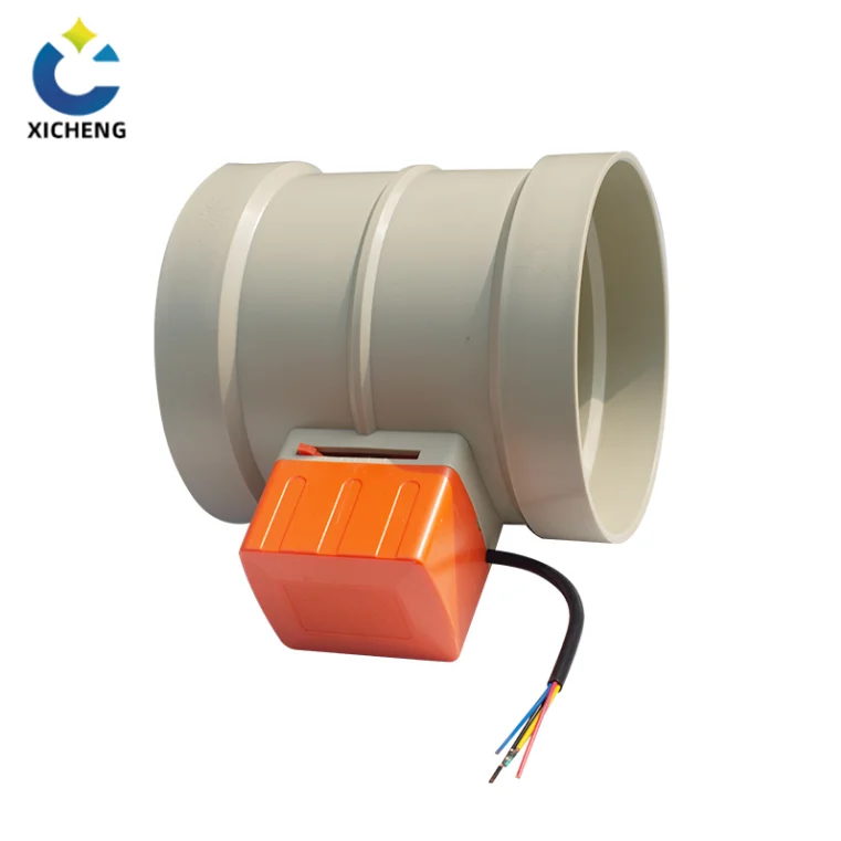
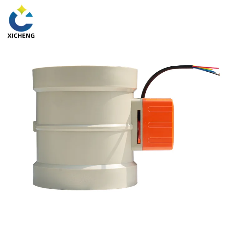
On a corrosion-resistant plastic duct system, the electric butterfly valve arrives as the motor head on a plastic air valve or damper: a small motorized quarter-turn disc valve bolted to a PP or PVC body that isolates or modulates the airflow. This is where the disc valve’s independence from compressed air earns its place, because the fume being moved is often the very chemistry that attacks a plant air system. Motorized plastic electric air valves commonly cover duct diameters from about DN50 to DN315, travel their 90 degrees in seconds from a 24 V or 220 V feed, and modulate continuously on a 0–10 V or 4–20 mA signal from the fume-control PLC. Away from the fume side, the same motorized quarter-turn damper on a fresh-air intake or a supply branch is the subject of the electric motorized damper guide.
Where the same duct must throttle airflow rather than simply isolate it, the electric butterfly valve body is exactly what the electric air valve product page carries, and the wider motorized assembly family is on the electric valves page. The chemical exposure limits that decide whether PP handles a given fume are explained in the polypropylene chemical resistance guide, and the duct integration side is in the plastic duct damper guide.
Installing, Maintaining, and Fail-Safe Operation
An electric butterfly valve that is sized correctly still performs badly if it is installed or commissioned carelessly, and its behaviour on a power failure must be decided before ordering rather than discovered after. The practices below follow the selection guides and install manuals used across the industry, and they prevent the failures that follow improper setup — distorted bodies, welded seats, end stops driven into the seat wall, and actuators left to hold an unplanned position.
Installing the Electric Butterfly Valve
Installation begins with the flanges. The pipe flanges must be parallel and concentric, because misalignment beyond about 1 mm can distort the valve body and cause seat leakage on resilient-seated valves. During welding on adjacent pipe, keep the disc in a partially open position so heat, slag, or spatter cannot damage the seat. After mounting the actuator, jog the valve manually to the fully closed position and adjust the close limit switch, then back off mechanically to prevent motor stall — a torque switch serves as secondary protection against an over-tightened seat. Mounting is done most safely with the valve closed, aligning the drive to the stem without power; the cams that set the open and closed stops are adjustable, so the stops can be fine-tuned to seat fully without driving past them.
Keeping It Reliable
A butterfly valve that stays in one position for months can develop stiction, so a control system that exercises infrequently operated valves by cycling them a small amount every 30 days — around 5 degrees — prevents sediment buildup and keeps the seat pliable. The primary stem seal, an O-ring or V-ring, wears with modulation, and an annual inspection catches a leaking stem seal before media corrodes the shaft or actuator adapter. Intelligent actuators log torque profiles on every stroke, and periodic torque monitoring reveals disc binding or seat wear long before a visible leak appears. For an electric butterfly valve held in storage, the same discipline applies as to any power valve: store it in a dry, ventilated area, keep the sealing ring out of contact with oily substances to avoid aging, and re-test a unit stored beyond roughly 18 months before installation.
Behavior on Power Loss
A standard electric butterfly valve fails safe only in the narrow sense that it holds its last position: the internal worm gearing self-locks, so the motor stops and the disc sits exactly where it was when power disappeared. That is valuable on a modulating valve but wrong for a fire-safety or chemical-isolation line that must close when power fails. To force a defined fail position — closed, open, or vented — the electric butterfly valve must carry a fail-safe mechanism such as a battery backup or an integrated supercapacitor that drives the disc to the safe position, or the site must provide DC or UPS power so the motor can finish its stroke. Define the required failure position before ordering, because the fail position is generally not changeable after delivery. A pneumatic butterfly valve provides a spring-return fail position for free, which is why air-powered units still hold ground on fire-safety duty; and on either type the manual override remains for commissioning and emergencies.
Electric Butterfly Valve FAQ
What is an electric butterfly valve?
An electric butterfly valve is a quarter-turn butterfly valve with an electric actuator bolted on top. The actuator’s motor and gear train rotate a circular disc through 90 degrees to open, close, or throttle the line, so the valve responds to a switch, a control signal, or a program instead of a hand on a handle. The three body components are a circular disc, a stem, and a seat, and the disc stays in the flow passage even when fully open, which gives the butterfly a small permanent pressure drop.
How does an electric butterfly valve work?
The control system sends a command such as a contact closure or a 4–20 mA signal. The electric motor spins, and the gear train reduces that speed into the torque the disc needs. The stem turns, and the disc rotates 90 degrees between fully closed and fully open. Limit switches stop the motor at the end of travel, a position transmitter reports the disc position back, and a manual override lets the valve be worked by hand if the actuator fails.
Electric or pneumatic butterfly valve: which is better?
It depends on what the plant already has. An electric butterfly valve runs on a power cable alone, draws no supply gas, produces no emissions, and automates directly from the control system’s own 0–10 V, 4–20 mA, or fieldbus signals. A pneumatic butterfly valve gives speed and a spring-return fail position from compressed air, but it needs a compressor, tubing, a solenoid, and the maintenance those bring. Electric is usually the better match where no instrument air exists — the normal case on plastic duct and fume plants.
Does an electric butterfly valve fail safe?
Only if it is specified to. A standard electric butterfly valve self-locks and holds its last position on a power loss. To fail to a defined safe position — closed, open, or vented — the valve must carry a fail-safe mechanism such as a battery backup or supercapacitor, or the site must provide DC or UPS power. Define the required failure position before ordering, because the fail position is generally not changeable after delivery.
What torque safety factor does an electric butterfly valve need?
Start from the valve’s published torque curve, split into breakaway torque — the force to move the disc out of its seated position, normally the largest figure — and running torque. Apply a safety factor of 1.2 to 1.5 times for standard service and at least 1.5 times for dirty, scaling, or viscous media, then check the actuator’s peak torque curve against the result. Pressure, temperature, and foul media all raise the demand, so size on the worst-case operating point, not the normal one.
Can an electric butterfly valve throttle flow?
Yes, if it is a regulating type with a modulating actuator and a positioner. The disc throttles best between about 20 and 70 degrees open; below roughly 30 degrees the flow is small and cavitation can damage the seat, and above about 70 degrees the flow curve flattens and control is lost. For continuous throttling, an eccentric high-performance or triple-offset body handles the wear of mid-stroke positioning better than a concentric resilient seat.
Key Takeaways
An electric butterfly valve is a quarter-turn disc body with an electric head: the disc stays in the flow passage even when fully open, so the installation gains speed, light weight, and roughly 70 percent less face-to-face space than a flanged ball valve, while accounting for a small permanent pressure drop the ball valve does not have.
Match the body family to the service before anything else — concentric resilient seats for clean, low-pressure lines; high-performance double-offset and triple-offset seats for steam, chemicals, high pressure, and zero-leakage duty — and choose wafer, lug, or flanged connections by the line connection and any dead-end requirement, because a lug valve’s rating drops in dead-end service.
Throttle only inside the control window — best controllability between about 20 and 70 degrees open — with a regulating electric butterfly valve and a positioner; near-closed angles invite cavitation and near-open angles lose control authority, so continuous throttling belongs on an eccentric or triple-offset body.
Size on worst-case breakaway torque with a 1.2 to 1.5 times safety factor, at least 1.5 times in dirty or severe media, and treat the valve and actuator as one system: a blind over-size factor loads the shaft, disc, seat, and gearbox as surely as an under-size stalls the disc.
Define the failure mode before ordering: a standard electric butterfly valve self-locks and holds its last position on power loss, and only battery, supercapacitor, spring, or UPS backup makes it fail to the closed, open, or vented position the process demands.
For a matched valve-and-actuator specification on a plastic duct, fume, or process line, the engineering team can size the electric butterfly valve body family, connection, torque, and control interface against the actual line conditions, and the electric valves range carries the compatible motorized assemblies.
