
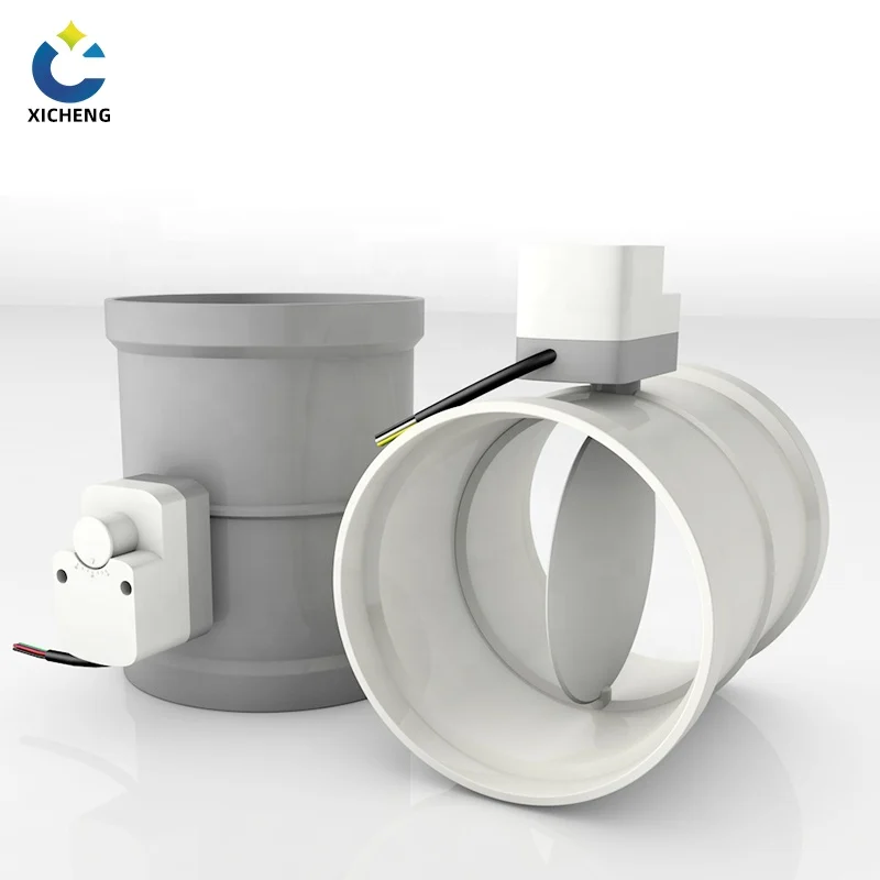
A manual valve actuator is the hand-operated mechanism that positions a valve: the lever, handwheel, gear operator, or locking device that turns the stem and moves the disc, ball, or blade. On a duct damper the manual valve actuator is the handle-and-quadrant assembly on the outside of the duct that sets the airflow; on an isolation valve it is the handwheel that opens and closes the gate. In both cases the manual valve actuator does the same job as any power actuator — position the valve — but it does it with a hand instead of a motor, which makes it cheaper, simpler, and immune to power loss.
The term sits inside a wider family. Valve actuator is the umbrella name for the positioning mechanism, and manufacturers split it into manual, electric, pneumatic, and hydraulic types. This guide covers the manual valve actuator in the depth it deserves: the common types, how the mechanism transfers force, how torque is sized, when a gear operator is worth the money, and how to select, install, and maintain one on valves and duct dampers alike.
Manual valve actuators earn their place wherever a system is balanced rather than continuously varied: HVAC and fume-extraction dampers, chemical dosing lines, water and air headers, and the branch take-offs of PP duct installs. Where a duct system is continuously varied by a thermostat or a building controller rather than balanced by hand, the drive moves to the electric motorized damper, which sizes the actuator together with the blade. They also serve as the mandated fallback on automated valves, because a handwheel path has to exist on every actuator that could lose power. Across all of these duties the pattern is the same — a trained hand sets a position in seconds, the mechanism holds it for years, and there is nothing electronic to fail. That consistency is why the manual valve actuator remains the default on low-voltage duct systems where a power actuator would add cost without adding control value.
What Is a Manual Valve Actuator?
Definition and role
A manual valve actuator converts a hand input on a lever or wheel into the rotation that positions the valve element. On a butterfly damper the actuator rotates the disc through 90 degrees; on a multi-turn gate or globe valve it rotates the stem through many turns to lift the closure member. The actuator also holds the position against airflow or process pressure after the hand releases it, which is where the locking and self-locking features of each type earn their keep.
Manual vs power actuation
A manual valve actuator is one member of the actuator family, and the Valve Manufacturers Association lists it first precisely because it is the simplest: it needs no power source, no wiring, and no control signal, and it cannot fail electrically. The trade-off is attention and speed. A power actuator adds remote control and repeatable automated positioning, which is why an electric valve actuator takes over where a controller must run the valve; the manual design stays on every valve that people reach comfortably with two hands. On duct duty the same reasoning points to an electric air valve, whose motorized blade answers the controller rather than a hand on a lever. The electric valve actuator guide covers the powered side of that hand-versus-motor decision in full.
Naming and scope of the term
Industry usage treats actuator and operator as overlapping labels for the same component: a manual valve actuator and a manual valve operator both mean the hand-operated mechanism bolted to the valve. What neither term covers is the valve itself — the disc, ball, or gate that the actuator positions — or the fittings that mount between them, which are selected in a separate sizing step. This guide likewise limits itself to hand power. Pneumatic and hydraulic actuators draw their force from a compressed-air or fluid supply, and an electric actuator uses a motor and a controller, so all three fall outside the manual definition even though many valve bodies accept each type in turn.
How a Manual Valve Actuator Works
The drive chain: handle to spindle to blade
Every manual valve actuator follows the same drive chain. The operator turns a lever or wheel, which rotates an input shaft, which drives a spindle through the valve body, which carries the disc, ball, or gate. On a quarter-turn butterfly damper the ratio is usually one-to-one and the handle travels the same 90 degrees as the blade; on a geared operator the ratio is multiplied through a worm or bevel set, so many small wheel turns produce one slow, high-torque valve turn.
Locking the position
Once the valve is set, the manual valve actuator must hold it. A lever operator relies on a locking quadrant — a slotted arc with a sprung pin or thumb screw — so vibration and flow cannot drift the blade. A handwheel or gear operator holds position through self-locking gearing, which means the mechanism cannot be back-driven by the valve. Without both functions any manual valve slowly changes set point on its own.
Position indication
Reaching the valve is not the same as knowing its position, so most actuators carry an indicator: the lever angle itself on a quadrant, a pointer over printed open and close marks, or a rising-stem indicator on a gate valve. On a duct damper the lever angle is most common, which is why commissioning marks are painted on the hub beside the quadrant.
Handle force and mechanical advantage
Everything a manual valve actuator does reduces to a torque balance at the hand. On an ungeared lever the operator’s force is multiplied only by the handle’s length: hold the same torque through a handle twice as long and the hand sees half the force, at the price of a wider swing arc and more space beside the duct. A gear operator changes the trade entirely, multiplying torque through the ratio of a worm or bevel set, so a short, slow wheel turn moves a high-torque valve that a bare lever could not. The tension between force and travel is exactly what sizing resolves, and it is why the same valve can feel effortless with a gear operator and impossible with a two-foot bar.
Types of Manual Valve Actuators
Lever and handle operators
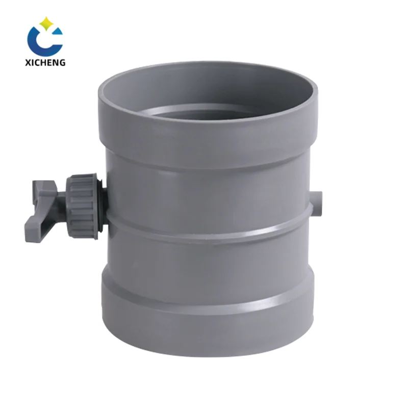
The lever operator is the everyday manual valve actuator on quarter-turn valves and duct dampers. One 90-degree swing of the handle moves the butterfly disc from closed to open, the locking quadrant fixes the intermediate positions, and there is nothing else to maintain. It is the standard on PP and PVC fume-system dampers and on the manual balance points of metal duct. Where the exhaust line must answer a controller or a code schedule instead of two hands, the electric exhaust valve guide covers the motorized actuator and blade for the job.
Handwheel operators
The handwheel is the multi-turn member of the family. It drives a stem nut or gear that lifts a gate or globe closure through many revolutions, giving fine, repeatable throttling on the last turns. Handwheels are self-locking, take no tools, and are specified on gate, globe, and needle valves where the operator must control flow closely and hold the opening precisely.
Gear operators
The gear operator adds a worm or bevel reduction between the wheel and the valve, multiplying hand torque so large butterfly valves, big dampers, and high-seat-friction duties turn with a reasonable effort. The price is speed — a geared manual valve actuator takes many wheel turns to travel the valve — which buyers accept in exchange for controlled force. Gear operators are the manual option on PVC and ductile-iron butterfly valves above about 8 inches, where a bare lever would hang too long and too heavy.
Declutchable gear operators
The declutchable gear operator is the hybrid that sits on automated valves. It bolts between the power actuator and the valve, with a clutch plate; when engaged, a handwheel drives the valve manually, and when disengaged the power actuator runs the valve. Max-Air’s explainer on the declutchable gear operator walks through the engage-and-disengage sequence that lets one mechanism work both ways. This is the manual valve actuator to specify when a duty is automated but must stay reachable by hand in an outage.
Locking and travel-stop accessories
Two accessories round out the family. Travel stops limit the blade travel so the valve cannot over-close into the seat, which protects soft seats on plastic dampers. Locking devices — padlockable quadrants, chain seals, or key interlocks — hold a valve in a mandated operating position and stop unauthorized movement. Neither changes how the actuator drives; both change what an operator is allowed to do with it.
Chain-wheel and extended operators
The last variant solves reach instead of force. A chain-wheel operator replaces the direct handwheel with a sprocket and chain that drops the operating point down to floor level on elevated butterfly valves and tank valves; an extended spindle or a jackshaft does the same job in a straight line behind an access panel. Both still count as manual valve actuators because power never enters the drive train. They earn their place only where a direct lever is unreachable, because every chain and shaft length adds backlash and two more maintenance points, and they are chosen after — not instead of — the reach check during selection.
Manual Actuators on Butterfly Dampers and Air Valves
The most common manual valve actuator in ducting is the lever-and-quadrant assembly on a butterfly damper, and it works identically on the molded PP version and the rolled metal version. The handle on our manual air valve range, described in our manual air valve guide, drives a spindle through the plastic boss, the quadrant holds the blade at the set throttle, and the lever angle is the position indicator. The same lever-and-quadrant pattern is described in our plastic duct damper guide, and it matches how metal duct suppliers fit locking quadrants to rolled-lip butterfly valves.
On larger duct faces and higher static pressures, the butterfly damper carries a gear operator instead of a bare lever, multiplying hand torque so the blade turns without a cheater bar. On automated fume systems the damper carries a declutchable operator so the control loop runs it in service and a technician can still move the blade by hand during a filter change or an outage, after a manual bleed valve vents the section first. The lever, spindle, and body in every PP case stay on the same material family covered in the PP material properties guide, so a lever that suits a Ø160 damper also suits the Ø160 duct flange it mounts between. The same butterfly range ships in flame-retardant PP in our PP duct damper line.
Placing the manual valve actuator is as deliberate as choosing it. Each branch take-off and riser balance point on a duct run wants its own lever at a height a fitter reaches without a ladder, with the handle axis clear of pipe mains and cable trays so the 90-degree swing is never blocked. On a fume line that means the lever sits beside the access panel, not behind it, and a chain wheel or extended spindle is only justified when the run genuinely forbids a reachable handle. Where a lever cannot be positioned safely, the manual valve actuator gives way to a motorized unit with a remote switch — reach, not price, makes that call.
Sizing and Operating Torque
The sizing question for any manual valve actuator is torque: how much hand effort the mechanism must convert into spindle torque to move the valve and hold it there. Underestimate it and the operator cannot turn the valve when it is loaded; over-engineer it and the money spent on gear reduction was unnecessary.
Quarter-turn vs multi-turn
Match the actuator motion to the valve motion. A butterfly valve or duct damper is quarter-turn: the disc travels 90 degrees, so a lever or a right-angle gear operator fits. A gate, globe, or needle valve is multi-turn: the closure rises and falls over many stem revolutions, so a handwheel with a rising stem or a geared set fits. Ordering a lever for a multi-turn valve or a handwheel for a quarter-turn damper is the most common actuator misselection in the trade.
Matching operator to blade area and seat friction
Torque demand grows with blade area, seat friction, pressure loading, and spindle-bush friction. A small PP duct damper turns with two fingers, a mid-size steel butterfly takes a geared handwheel, and a high-pressure process valve takes a large geared unit, and a lever-opened ball valve on a fuel-gas line shares that quarter-turn motion, which the manual gas valve guide covers. Table 1 is the working summary.
| Actuator type | Motion | Typical valve / damper | Output advantage |
|---|---|---|---|
| Lever and quadrant | Quarter-turn 90° | Small butterfly, duct damper, ball valve | Economical, fast, no tools |
| Handwheel | Multi-turn | Gate, globe, needle valve | Fine throttling, self-locking |
| Worm gear operator | Quarter- or multi-turn | Large butterfly, big damper, high-friction seat | Turns torque multiplication |
| Bevel gear operator | Quarter-turn | Ball and butterfly on right-angle layouts | Re-directs handwheel position |
| Declutchable gear | Either | Automated valve with manual fallback | Manual override on power drive |
Calculating the required torque
The sizing sum is four terms: torque to overcome seat friction, torque from pressure loading on the closure, torque from spindle-bearing friction, and a service factor for material aging and deposit buildup. For a quarter-turn PP duct damper the working line is short — read the blade torque at the highest static pressure the system sees, add the seat friction at the closed position, then apply a 1.25 to 1.5 service factor and select an operator whose rated torque exceeds the result. A worked example: a Ø160 PP damper at 1,500 Pa with a light PP seat can ask for roughly 3 to 5 N·m at the stem, and a locking lever on a 200 mm handle delivers that comfortably; the same blade at 4,000 Pa in a loaded fume run climbs toward the mid-range where a short gear operator is the safer call than a longer bar.
Effort at the handle and wheel
After the torque sum, check the human side: the effort a fitter can sustain across a working day, not just on one turn. As a working guide, a quarter-turn lever should open and close a repeated balance position with one hand and no cheater bar; a handwheel in constant use should stay within the lengths most operators turn without body weight; and a gear-wheel duty raises multiplication precisely so nobody reaches for a pipe wrench. If comfortable effort does not fit the layout, the answer is a longer lever, a gear step, or a smaller operator on the neighboring tap — never a silent workaround that leaks into maintenance later.
Manual vs Electric Actuator: When Each Wins
The manual valve actuator wins the first-cost and reliability argument whenever a valve is set rarely and reached easily. It has no motor, no gears to strip under a stalled signal, no limit-switch wiring to chase, and no power budget; the maintenance check is a grease point and a wipe instead of an actuator teardown. The ValveMan explainer on the valve actuator family puts the manual member in context against electric, pneumatic, and hydraulic designs.
Electric becomes the right answer when the valve must respond to a controller, move on a schedule or an interlock, or sit beyond the reach of personnel. Where the valve body is a butterfly, the electric butterfly valve guide carries that automated disc valve. The electric valve guide covers the motorized side of that decision in full. Those duties are covered by the electric valve family in this cluster, and the same valve body accepts either the manual lever or a direct-mounted motor. Specify a declutchable gear in between when you want automation with a guaranteed manual fallback.
A second argument comes from service life. A manual valve actuator carries a handful of wearing parts — a bush, a pin, a latch — and none of them fails electrically, so a well-lubricated manual unit routinely outlives the motorized unit beside it and costs a fraction to overhaul. That changes the buying decision: on low-power duct systems the manual valve actuator is usually the right first purchase, and the same valve body takes an electric actuator later without re-specifying the valve. The manual start is a hedge, not a dead end.
A useful rule of thumb: if an operator can reach the valve and the position changes fewer than a few hundred times a year, the manual valve actuator is usually the lower lifetime cost; if the position is driven by anything except a person, go electric.
How to Select a Manual Valve Actuator
Selecting a manual valve actuator is a three-question exercise: what does the valve do, how much torque does it need, and where does the mechanism have to fit. Answer those three and the actuator type picks itself.
By duty
State what the valve must do: balance throttle, hard isolation, or infrequent open-close. Balancing points take a lever with a locking quadrant; isolation duties take an operator whose closing force and travel stop can close the valve positively; routing duties take a diverter or multi-port operator.
By torque
Read the valve torque curve at the highest pressure the system sees, add the seat friction and a service factor, and select the actuator that exceeds it. If the required effort at the handle is comfortable, the geometry fits; if the valve needs a long bar or two people, step up to a gear operator. Table 2 gives the manual operator choice for common duct sizes.
| Duct / valve size | Recommended manual operator | Notes |
|---|---|---|
| Up to Ø160 duct damper | Lever and locking quadrant | Light effort, lever angle = position |
| Ø200 – Ø315 duct damper | Lever, or gear on high static | Check effort at system pressure |
| Butterfly up to about 8 in | Lever and quadrant | Standard industrial choice |
| Butterfly above about 8 in | Worm gear operator | Torque multiplication, safe effort |
| Gate / globe valve | Handwheel, multi-turn | Fine throttling, self-locking |
| Automated valve with fallback | Declutchable gear operator | Manual override on the power drive |
By material and chemistry
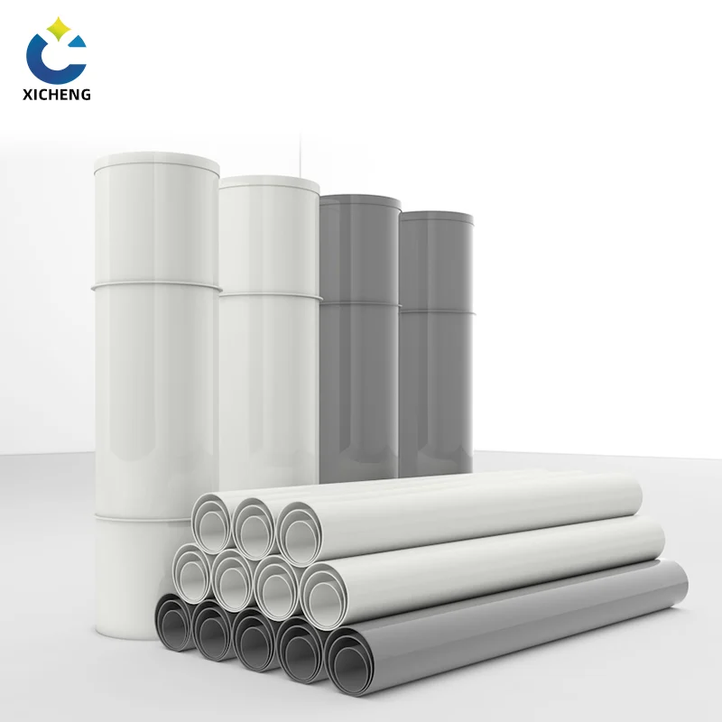
Material compatibility limits every non-metallic actuator just as it limits the valve, and on plastic duct systems the rule is to keep the whole actuation point on one material family. PP levers, spindles, and quadrant assemblies — in the plain and flame-retardant grades covered in the PP sheet range — suit fume, scrubber, and chemical exhaust lines where a galvanized handle would corrode; where the media is a strong acid or solvent the check widens to O-rings and spindle seals, not just the body. Temperature matters second: PP parts hold their stiffness across the same moderate service band as the ductwork around them, while a metal body on the same valve relaxes that limit for hotter and heavier duties.
By space and reach
The last check is physical. The manual valve actuator needs room to swing: a lever travels a 90-degree arc beside the duct, a handwheel needs clearance for a gloved hand, and a gear operator needs its wheel plane reachable. On fume lines the whole assembly stays inside the PP sheet and fabrication material set, and for a valve that cannot be reached, note the reach constraint and mount the actuator above, not beside, the valve. For a specific valve or duct, send the size, pressure, and duty to our engineering team and take the manual operator recommendation before ordering.
Installation and Maintenance
Mounting
Install the manual valve actuator on the valve stem or hub using the manufacturer coupling, align the lever or wheel to the valve travel, and set the travel stops to the correct open and close positions before the system is pressurized. On duct dampers, mount the handle on the side a technician can reach, verify the blade travels its full range with the handle, and do not use the actuator as a pipe support or a ladder point.
Lubrication and inspection schedule
A quarterly service covers the essentials: re-tighten the quadrant pin or thumb screw, lubricate the spindle bush and gear teeth with compatible grease, check for wear on the lever hub, and confirm the position indicator still points where the blade actually is. Gear operators get a seal and level check, declutchable units get an engage and disengage test, and plastic-duct actuators get a soft-brush clean of debris that could score the seat. Record the commission mark after every service so the balance stays repeatable.
Common faults and troubleshooting
A failing manual valve actuator almost never surprises if the quarterly check is kept. Drift in a set point points to a loose quadrant pin or a worn lever latch, and the fix is re-tightening or replacing the pin. A hard-to-turn spindle after a shutdown points to corrosion or dried grease on the bush, which a compatible lubricant and a few exercises usually clear. A handle that spins freely while the blade stays stuck is a sheared hub key or a stripped quadrant slot, and the repair is the replacement coupling, not force. When an automated valve walks its setting, test the declutchable gear’s clutch-plate meshing before blaming the motor. Every fault has a stock cause; logging what you fixed keeps the next service twenty minutes shorter.
Manual Valve Actuator FAQ
What is a manual valve actuator?
A manual valve actuator is the hand-operated mechanism that positions a valve — a lever, handwheel, or gear operator that turns the stem and moves the disc, ball, gate, or blade. It needs no power source and holds its position through locking or self-locking hardware.
What is the difference between a manual and an electric valve actuator?
A manual valve actuator is positioned by hand and costs the least; an electric valve actuator uses a motor and a control signal to position the valve automatically. Manual wins on price, simplicity, and reliability at reachable balance points; electric wins on remote control, scheduling, and process interlocks.
When should I use a gear operator instead of a lever?
Use a gear operator when a bare lever or handwheel cannot generate enough torque comfortably, typically on larger butterfly valves, bigger dampers, or high-seat-friction duties. The gear multiplies hand effort at the cost of more turns.
Does a manual valve actuator need power?
No. A manual valve actuator works without electricity, air, or hydraulics, which is why it is the fail-safe answer for outage positioning and why automated valves bolt on a manual gear override when a hand path must exist.
Can a duct damper be operated manually after it is motorized?
Yes, when the damper uses a declutchable gear operator the electric actuator runs the damper in service and a handwheel engages for manual operation during maintenance or power loss. The same body also accepts a plain lever if it was never motorized.
Key Takeaways
• A manual valve actuator is the hand-operated positioning mechanism — lever, handwheel, or gear operator — that turns the stem and moves the valve element without any power source.
• Lever-and-quadrant is the standard on quarter-turn duct dampers; a handwheel suits multi-turn valves; gear operators multiply torque for large or high-friction duties; declutchable gears add a manual fallback to automated valves.
• Size the actuator by torque at the highest system pressure, plus seat friction and a service factor; never put a lever on a multi-turn valve or a handwheel on a quarter-turn damper.
• Manual wins on cost and reliability at reachable, rarely changed positions; choose electric only when a controller, schedule, or interlock must drive the position.
• Keep the whole actuation point on the same material family as the valve, so the lever, spindle, and PP body stay compatible with the duct series.
