
A manual gas valve is the hand-operated shutoff that positively stops or meters the flow of fuel gas in a piping system. Whether it is a quarter-turn ball valve on a furnace branch, a lubricated plug valve on a meter set, or a multi-turn gate valve isolating a burner train, the mechanism is one idea in different bodies: a person turns a handle, the stem moves a sealing element into or out of a seat, and the line is open, closed, or set somewhere between the two under that person’s control. It is the most direct member of the valve family covered on this site, alongside the plastic duct damper, the manual air valve guide, and the manual valve actuator guide.
For any line that carries natural gas, LPG, or fuel gas, understanding how a manual gas valve works is the difference between a plant that isolates cleanly for maintenance and a plant that cannot stop a leak in a hurry. This guide explains the operating mechanism, the valve types, the approval and location rules that govern where a manual gas valve may be installed, and how to select, operate, and test one. If the application calls for a corrosion-resistant manual valve on a PP duct or fume sampling line, the manual air valve product page shows the compatible range.
What Is a Manual Gas Valve?
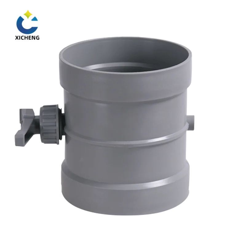
Definition and family position
A manual gas valve is a hand-operated device that starts, stops, or throttles the flow of a fuel gas — natural gas, LPG, or manufactured gas — through a piped system. It has no solenoid, no thermostat, and no motor: the operator’s hand is the actuator, and the valve holds whatever position the handle was last left in. Where that gas line must open and close on its own, the electric valve actuator guide covers the motor-driven side of automatic valve operation. That simplicity is its value. Across the valve family on this site, the manual air valve handles compressed air and ventilation service, the manual bleed valve vent and drains a pressurized section, and the manual gas valve does for combustible gas what those do for air and condensate — it gives a person a positive, predictable point of control. It is the valve a gasfitter reaches for when a pipe must be isolated so that a burner, a regulator, or a length of tubing can be serviced without the line feeding gas into the work.
The two operating motions
Manual gas valves fall into two groups by the motion the handle makes, and that motion decides how much flow control the valve offers. The distinction matters because it maps onto the two jobs a gas valve does: positive shutoff and throttling.
Quarter-turn: ball and plug valves
Ball valves and plug valves open and close in a quarter of a turn of the handle. Inside, a ball with a hole through its centre, or a tapered plug with a passage, is rotated so the bore either lines up with the pipe (open) or faces the pipe with solid material (closed). The quarter-turn gives a fast, unmistakable shutoff, and the handle position is a reliable indicator — parallel to the pipe is open, perpendicular is closed. Most gas shutoff applications below two inches are handled by lever-operated ball valves of this kind.
Multi-turn: gate, globe and needle valves
Gate, globe, and needle valves move a disc, wedge, or tapered stem straight into a seat by spinning the handle several turns. The multi-turn motion gives fine control, so globe and needle valves are the ones chosen to set a flame rate or meter a pilot flow, while a gate valve is the classic multi-turn shutoff for larger lines. The cost of that control is speed and ambiguity: closing takes many turns, and the handle position does not tell you the valve position the way a quarter-turn lever does.
Where a manual gas valve sits in a gas system
A conventional gas installation carries a small chain of manual gas valves at fixed points. A meter valve sits on the supply side of the utility meter; regulator valves isolate pressure-reducing stations; appliance shutoff valves sit in the same room as each appliance, within reach of it; and manifold valves divide a larger run so one branch can be worked on without draining the rest. Between these fixed points the piping is threaded, welded, or flared, and the valve bodies are sized and rated to match the pipe and the service pressure. Because every one of these valves is a deliberate, physical interruption in the line, the system cannot reset itself — the room stays gas-free until a person opens the valve again, which is exactly the guarantee maintenance and emergency work rely on.
How a Manual Gas Valve Works
The quarter-turn path: ball into seat
Opening a lever-operated ball valve is a single movement: a ninety-degree rotation of the handle swings the stem, and the stem rotates a ball that has a round bore drilled through its centre. When the bore lines up with the pipe openings the gas flows straight through; when the handle is turned to the stop, the ball’s solid face presents to the flow and the seat rings around it seal the line. The sealing is mechanical — the ball is squeezed between two seat rings, in most gas service a brass or chrome-plated ball against Teflon seats, with the compression provided by tightening the body halves or the end fittings against each other. The whole path is short, which is why the ball valve closes positively even after years of little use: there is no long threaded stem to wear, only a fixed ball and two seats.
Body, stem, and seats
The parts that do the work are few. The body carries the inlet and outlet connections and holds everything in alignment; the stem passes through the bonnet or top of the body to the handle and turns the ball; the two seats are the soft rings that seal against the ball in both directions. A packing gland around the stem keeps gas from leaking up the stem to the handle. Two-piece bodies hold the ball and seats by threading the two halves together, while one-piece bodies use a retaining clip and washer so that the parts can be serviced from one end. Because fuel gas service takes the seal directly, the materials must be rated for it — brass bodies and chrome-plated brass balls are standard for residential and commercial shutoff duty.
Handle alignment: parallel is open
The lever is more than a handle; it is an indicator. On a quarter-turn manual gas valve the stem and the lever are keyed to the ball bore, so the lever lies parallel to the pipe when the valve is open and perpendicular to it when closed. Operators rely on this at a glance, and code bodies expect it — a person isolating an emergency should be able to see, without touching anything, whether a line is live. Gas-rated handles are often coloured yellow so that they stand out from the brass body and the surrounding pipework, and locking handles with a notch and hole let a valve be pinned shut so that it cannot be opened by accident during a shutdown. The quarter-turn operation and the lever-and-bore alignment behind this indicator are laid out step by step in SkilledTradesBC’s describe-manual-valves chapter, which is the reference for the valve-operation diagrams used here.
The multi-turn path: stem into seat
Where a quarter-turn valve rotates a ball past the flow, a multi-turn valve moves a flat disc, wedge, or needle straight into the stream. The operator spins a handwheel, and a rising spindle either lifts the disc clear of the flow or lowers it into a seat ring until the line is tight. Because the stem is threaded, the valve can stop at any point along the travel, which is what lets a globe or needle valve hold a set flow rather than only open and shut.
Gate and globe action
A gate valve seals with two flat seats and a wedge that drops between them; fully open, the wedge lifts clear so the pipe bore is unobstructed, which is why gate valves suit lines that must pass full flow at low pressure drop. A globe valve seals through an internal seat that the disc closes against across the flow direction; the route through the body is the classic S-shaped bend, which creates a measurable pressure drop but gives precise control of partial flow. On fuel gas systems the distinction is safety-driven: a gate valve, correctly seated, is a positive shutoff, while a globe valve is usually the regulating member in a system that has a separate shutoff elsewhere.
Throttling versus shutoff
It is worth stating the rule plainly because it decides valve selection on every burner train: throttling valves — globe, needle, and butterfly types — are for setting flow, not for proving the line is off. They can be left cracked open, and a needle barely off its seat still passes a pilot-size flow, so a technician cannot treat a needle valve as proof of isolation. Gas codes therefore require a listed manual shutoff valve, ball or plug type or equivalent, installed upstream whenever a throttling valve serves a burner. The shutoff proves the line is dead; the throttling valve then sets the rate.
How lubricated plug valves hold their seal
The lubricated plug valve keeps its seal by an active film rather than by a soft seat. The plug is tapered and ground into a matching seat in the body, and a groove system carries a sealant that the operator injects through a lube port in the body or the top of the plug. The sealant film fills the clearance between plug and body, dresses the contacting surfaces, and makes the plug turn smoothly without galling. The practical payoff is that the valve can be relubricated in place — with the valve in the line and the system still on — by injecting a measured shot of sealant, which is why utility meter sets favour this type: maintenance does not interrupt the service. The plug opens and closes in a quarter turn like a ball valve, and the unlock lever lifts the plug an instant before rotation so the sealant film is not wiped off on every cycle.
Reading a manual gas valve
Every certified gas valve carries its story on the body in stamped or bonded markings, and matching those markings to the service is how a gasfitter proves a valve belongs where it is being fitted. Two families of marking matter.
WOG, WSP, and G ratings
WOG stands for Water, Oil, and Gas and CWP for Cold Working Pressure; both state the non-shock pressure the valve will hold at ambient temperature. The catch is that the “Gas” in WOG means air and nitrogen, not combustible gas — a 600 WOG ball valve is not automatically approved for fuel gas service. Combustible-gas approval is carried by the G markings: ½ PSIG (or ½ G) for appliance shutoff service, 5G for interior gas distribution, and 125G for gas piping systems at up to 125 pounds per square inch. A valve marked both WOG and G carries both ratings, and the certified gas pressure is the lower, specific one.
UL, CSA, FM, and CGA marks
The approval stamps tell you who tested it. UL, Underwriters Laboratories, tests valves to three times the stated pressure rating to earn its mark; CSA, the Canadian Standards Association, certifies to both Canadian and US standards and may add a C or US under its logo to say which; FM, Factory Mutual, tests from an insurance-engineering standpoint; and CGA, the Compressed Gas Association, covers industrial, medical, and food gas applications. A valve approved for fuel gas will carry one or more of these, and the body marking takes precedence over a vendor’s catalogue claim when the two disagree on the site.
Manual vs Automatic vs Combination Gas Valves
Three control philosophies
A manual gas valve is opened and closed by a person — a knob, lever, or handwheel — and holds its last position until someone changes it. That makes it simple, predictable, and cheap, which is why basic cookers, portable grills, and fryers run on nothing else. Automatic gas valves replace the hand with a thermostat, timer, or sensor that opens and closes the valve on demand, which buys precise temperature control and flame supervision for ovens, heaters, and commercial appliances. The electric valve guide covers the motorized and solenoid variants of automatic valve control. Combination gas valves take the automatic idea further by stacking several jobs into one body: gas flow control, safety shutoff, pressure regulation, and pilot or main burner ignition, working with an ignition module that lights and watches the flame, as found in fireplaces, water heaters, and furnaces. The same three-way division is set out in Grand Mate’s comparison of manual, automatic, and combination gas valves.
When the manual valve is the right choice
The manual gas valve is the right choice whenever the operator must be able to say, with certainty, that the gas is off. A combination valve will cut flow on its own when a sensor trips; a manual valve cuts flow only when a hand turns it, but it also stays off only when a hand turns it back on — nothing resets it silently. That is why every building and plant that runs gas keeps a manual shutoff valve upstream of every automatic and combination valve: the automatic valve manages the appliance day to day, and the manual valve guarantees isolation for service and for emergencies. Forecasters buying new equipment should not read “automatic” as a replacement for the manual shutoff. The two are partners, one for control and one for proof of isolation.
How the choice affects commissioning
The split also shows up at commissioning and service. A plant fitted purely with automatic valves is, in practice, operated at the mercy of its sensors: the loop that lights the pilot, proves the flame, and opens the main valve has to be exercised, and a smart valve that has lost its calibration profile can sit dead while the technician suspects the burner. A manual gas valve in the same train removes that ambiguity — the operator closes the manual valve, works on the burner with the line proven dead, and opens it again with a fixed, physical restart that needs no electronics to hold. System designers who keep one manual shutoff per appliance keep the ability to work on the ladder of automatic controls without fighting them. The exhaust side holds the same principle in the electric exhaust valve guide, where a code-required motorized shutoff and its manual backup let a line be proven closed with power off.
| Valve type | Method of control | Control authority | Typical duty | Common locations |
|---|---|---|---|---|
| Manual gas valve | Hand-operated knob, lever, or handwheel | The operator | Positive shutoff, occasional throttling | Meter, regulator, appliance shutoff |
| Automatic gas valve | Thermostat, timer, or sensor | The thermostat or sensor | Demand-based flow control, precise temperature | Ovens, heaters, commercial appliances |
| Combination gas valve | Ignition module plus built-in regulator and safety | The ignition control system | Flow control, safe lighting, flame supervision in one body | Fireplaces, water heaters, furnaces |
Types of Manual Gas Valves
Ball valves — the workhorse shutoff
The lever-operated, non-lubricated ball valve is the most common manual gas valve used for appliance shutoff in residential and commercial service. The body is usually brass, the ball chrome-plated brass, and the seats Teflon, with smaller sizes sometimes using O-rings. Operation is a quarter turn of the lever, the bore through the ball is the full internal size of the connection on a full-port valve, and the handle reads open and closed at a glance. Ball valves pay for that simplicity in two ways: they are either open or shut, with no real throttling position, and their soft seats can age, but for shutoff duty nothing is easier to operate or to verify. The damper family on this site pairs the same quarter-turn thinking with PP bodies for ventilation service.
Plug valves — lubricated, quarter-turn shutoff
Plug valves shut off with the same quarter-turn motion but replace the ball with a ground, tapered plug. Non-lubricated plug valves, brass and spring-loaded, were common for indoor low-pressure gas service in the past; today the lubricated type carries the bulk of the work, especially on outdoor meter installations where it is maintained by the gas utility. The lubricated plug valve’s sealant film gives it a leak-tight seal and free turning at the same time, and its groove system lets it be relubricated in place with the valve in service. Because the plug seal is metal-to-metal rather than soft, plug valves tolerate higher temperatures and repeated cycling better than ball valves of the same size, which makes them the standard choice on meter sets and in plant distribution lines.
Gate valves — the multi-turn shutoff
Where a line must be isolated with a wide-open, full-bore passage when the valve is open, a gate valve is the classic answer. The handwheel lowers a wedge between two seat faces to close, and lifts it clear to open, so the valve imposes almost no pressure drop when passing full flow. Gate valves have two practical drawbacks on gas work: they are slow, needing many turns from open to closed, and they give no visual cue of position — a wheel spun forty turns does not show whether the gate is seated. They remain common on larger lines and on plant utility headers where a positive, full-opening isolation is required and speed of operation is secondary.
Globe, needle, and butterfly valves — throttling duty only
Globe, needle, and butterfly valves are the regulating members of a gas system, sometimes called firing-rate or limiting-orifice valves because they set how much gas a burner receives. A globe valve closes a disc into a seat across the flow and gives fine control of partial flow; a needle valve is a globe built with a long, tapered stem for pilot-sized flows; a butterfly valve throttles with a rotating disc and finds most of its large-line duty in combustion air and gas trains. On the duct side of the same family the rotating disc becomes an electric air valve when duct airflow must modulate under power. None of the three is a positive shutoff: each can be left partially open, and a needle valve eighty per cent open still passes gas. The safe design rule is fixed: fit an approved manual shutoff valve upstream of any throttling valve, and use the throttling valve only to set the rate, never to prove the line is off.
Shutoff valves versus throttling valves
The two families support one rule that governs every selection: ball and plug valves, and gate valves for larger lines, are shutoff valves; globe, needle, and butterfly valves are throttling valves. A throttling burner is set with a needle valve, but the line that feeds it is proved dead with a ball valve fitted upstream, and the two are never interchanged on a gas train. Table 2 summarises the family so the distinction can be checked at specification time.
| Valve type | Operating motion | Sealing element | Duty on gas systems | Typical use |
|---|---|---|---|---|
| Ball valve | Quarter-turn | Bore-drilled ball between Teflon seats | Positive shutoff | Appliance shutoff, plant branch isolation |
| Plug valve (lubricated) | Quarter-turn | Ground tapered plug with sealant film | Positive shutoff | Meter sets, distribution line isolation |
| Gate valve | Multi-turn | Wedge lowered between two seat faces | Positive shutoff, full bore | Larger lines, utility headers |
| Globe valve | Multi-turn | Disc closed into a seat across the flow | Throttling | Burner flow adjustment |
| Needle valve | Multi-turn | Tapered stem into a narrow seat | Throttling, pilot flows | Pilot gas, instrument lines |
| Butterfly valve | Quarter-turn | Rotating disc across the bore | Throttling | Combustion air and gas trains |
Standards, Locations and Approval
The appliance shutoff rule
The governing idea across national gas codes is that every appliance must have its own manual gas valve, installed so that a gasfitter can isolate that single appliance without interrupting the rest of the building. In the International Residential Code’s Fuel Gas chapter, Section G2420, Gas Shutoff Valves, the appliance shutoff valve must be located in the same room as the appliance, within 6 feet (1829 mm) of it, and installed upstream of the union, connector, or quick-disconnect device it serves, with access for operation. The Canadian CSA B149.1 code expresses the same requirement: a readily accessible shutoff valve for each appliance, typically placed just outside the appliance where it can be reached for service. The 6-foot rule is the one most often quoted from memory, and it exists so that a person standing at the appliance can reach the valve that kills its gas supply.
Meter, regulator, and manifold valves
Beyond the appliance there is a ladder of isolation. Every meter must carry a shutoff valve on its supply side so the utility can cut the whole premises; where pressure-regulating stations are installed, a listed shutoff valve sits immediately ahead of each medium-pressure regulator so the regulator can be changed without feeding the work from the street; and on a system serving more than one building, shutoff valves must be installed outdoors at each building. Where several appliances are fed from a manifold, the manifold shutoff valve may be up to 50 feet (15,240 mm) from the appliance it serves, provided it is readily accessible and permanently identified. The pattern is consistent: valve where the meter enters, valve before each regulator, valve at each building, valve at each appliance — and every valve in a place a person can actually reach.
Prohibited locations and documentation
Codes also say where a manual gas valve may not go. Shutoff valves are prohibited in concealed locations and in furnace plenums, because a valve buried in a wall or cased in a duct is a valve nobody can operate in an emergency — the code’s phrase is that a shutoff valve must be provided with access for operation and protected from damage. The valve itself must be an approved type, constructed of materials compatible with the piping, and compliant with the standard applicable for the pressure. The approval matrix is enforced by the markings: ANSI Z21.15 valves serve appliance shutoff service up to ½ psig, ASME B16.44 covers valve applications up to 2 or 5 psig depending on the label, and ASME B16.33 extends to 125 psig gas piping. Read the body — a WOG-only valve has no business on a fuel gas line no matter what its pressure number says, because the approvals that appear on the handle or body are the record an inspector will verify.
How to Operate and Test a Manual Gas Valve
Open and closed: how to read the handle
On a quarter-turn manual gas valve the position is written on the handle. Lever parallel to the pipe means the bore is aligned and the valve is open; lever perpendicular means the ball or plug has turned to present its solid face and the valve is closed. This is why operators are taught to glance at the handle before touching anything — in a multi-appliance plant a row of shutoff levers should all read the same way on a shutdown, and a single lever lying crosswise is either the valve that isolates the work or the accident waiting to be opened. On multi-turn valves the same cue does not exist, so the discipline is procedural: close the valve fully, then tag it, then prove the line dead with a gauge or a downstream flame test rather than trusting the handwheel position. When a lockable handle is fitted, pinning the lever shut makes the isolation physical so that nobody can open it without deliberately removing the lock.
The soap-bubble leak test
The standard field test for a gas valve connection is the soap-bubble test. A soap-and-water solution is brushed or sprayed over the joint between pipe and valve, over the valve bonnet or packing nut, and over the handle gland; if gas is escaping, it blows a bubble or a foamy patch in the wet film. The procedure is simple enough for maintenance staff, but the reading of it is precise: a steady stream of bubbles at a threaded joint means the thread seal has failed and the joint must be remade, while bubbles at the packing nut mean the stem packing is leaking and the packing can often be tightened a quarter turn before resorting to replacement. On lubricated plug valves the same test verifies the sealant film — a valve that foams at the top and bottom O-ring seats needs a fresh shot of sealant, not a new valve. Bubbles anywhere on a fuel gas line are a stop-work event, not a follow-up item.
Signs of wear and when to replace
A manual gas valve speaks its age through its handle. A ball valve that has become hard to turn has a seat or stem packing problem, not a flow problem; if it turns hard in only one direction, the seat on that side has begun to degrade and the valve is on its way to leaking past the ball. A plug valve that turns roughly, or returns a gritty feel through the handle, has lost its sealant film and needs relubrication; if relubrication does not restore smooth travel, the taper has worn and the valve should be replaced rather than forced.
A gate valve that will not seat with a normal two-handed effort may have a worn wedge or scale in the seat track — forcing it further risks cracking a casting. The replace threshold is simple: any valve that leaks past its seat when closed, or leaks through its packing when closed, has failed its duty as a positive shutoff. On fuel gas the correct response is shutdown of the line, replacement of the valve, retest with soap solution, and re-commissioning — not a patch, and not a stronger hand. Where a service cannot wait, the engineered answer is a valve that matches the line’s duty and materials from the start, the same way the manual valve actuator guide matches an actuator to its damper. On the ventilation side of the same system, the damper that answers a controller rather than a handwheel is the electric motorized damper, covered in a guide on fresh-air, zone, and supply duty.
How to Choose a Manual Gas Valve
By media and pressure rating
Selection starts with what the valve will carry and at what pressure. Natural gas distribution in buildings runs at fractions of a pound per square inch up to a few pounds; LPG and propane service runs hotter and carries a higher vapour pressure; and industrial fuel gas trains can hold hundreds of pounds. The body marking is the contract: ½ PSIG or ½ G for appliance shutoff, 5G for interior distribution, 125G for gas piping, and WOG for water-oil-gas service that does not include combustible gas. A plant engineer buying a valve for an appliance branch chooses a ½ G ball valve; the same engineer feeding a burner train from a 100 psig header chooses a 125 G or an ASME B16.33 valve, and reads the UL, CSA, FM, or CGA mark to confirm which standard’s test the valve actually passed.
Appliance, distribution, and piping grades
The three ratings map to three physical jobs, so the grade should match the line, not the budget. Appliance-grade valves (½ G) seal at the low pressure they see and are sized small; distribution-grade valves (5G) are built for the higher pressures of interior piping runs and meter sets; piping-grade valves (125G) carry the highest long-term loads. Fitting a lower grade on a higher-pressure line is the failure that shows up as a weeping stem packing or a seat blow-by after a few years, and it is the failure an insurer’s FM approval is designed to prevent — the valve that carries FM was engineered to endure its rating with margin.
By size and connection type
Once the pressure grade fits, the size and the end connections decide what threads satisfy. Manual gas valves in the industrial range run from 1/8 inch up to 4 inches nominal in the common commercial sizes, with larger flanged valves on plant headers. The end connection is chosen to match the piping: female NPT (FNPT) threads for steel or black-iron pipe, male flared ends for the annealed copper tubing used on many appliance drops, and combination ends on transition pieces. The connection is not cosmetic because the thread seal on a gas line is the joint itself — a NPT connection depends on the taper of the thread and the threaded sealant, while a flare connection depends on the geometry of the faces.
FNPT and flare ends
Female NPT is the default for threaded pipe: the valve screws onto a male pipe end, the taper jams the threads together, and the fit must be gas-tight on its own because there is no gasket. Flared ends suit copper and flexible tubing, where the tubing end is flared to a cone and a compression nut presses it against the valve’s matching cone. Mixing the two is a common installation error — a flare valve forced onto a NPT nipple, or a pipe sealant slugged onto a flare face — and both violate the code’s requirement that the valve be constructed of materials compatible with the piping and installed to the standard.
Full port versus reduced port
A full-port ball valve has a bore through the ball the same size as the pipe’s nominal bore, so the open valve adds nothing to the system’s pressure drop. A reduced-port (standard-port) valve carries a ball opening one pipe size smaller, which costs some flow capacity but lets a smaller, cheaper valve body serve the line. Full port is the right answer on burner feed lines where the burner is sized for the pipe’s full flow and on lines where pressure drop matters; reduced port is acceptable on short shutoff runs where the drop is within the train’s design margin. The two are marked differently on the spec sheet, and the port size is one of the first details a gasfitter checks when a burner starves after a change of valve.
By duty: shutoff or throttling
Duty decides the family. If the valve must prove the line dead — appliance isolation, branch isolation, emergency shutoff — choose a positive shutoff valve, ball or plug for the 1/8-to-4-inch range or gate for larger lines, and verify its shutoff duty and approval marks. If the valve must set a flow rate — pilot gas, instrument supply, burner firing rate — choose a throttling valve, globe or needle, and always install the required shutoff valve upstream that you use for isolation. Weighing the two against each other in the same specification check is exactly the choice the earlier comparison of shutoff and throttling valves is meant to settle, and it prevents the most common misspecification of gas train hardware.
Materials from brass to PP
Brass is the workhorse body material for gas valves because it machines well, threads cleanly, and resists the mildly reducing atmosphere of natural gas and LPG. Steel and ductile iron appear on larger and higher-pressure lines, and bronze appears where the fitting mates with copper piping to avoid galvanic corrosion. There is one further material step that matters on this site’s territory: where a gas or fume sampling line runs through a corrosive ventilation system, the valve body should match the duct material for the same reason the run is PP — the acid fume that eats a cast body at a weld will eat it at a valve seat, and a polypropylene-bodied manual valve, like the manual air valve in the PP range, keeps the corrosion resistance of the duct through the point of control.
Material selection is therefore not the last item on the spec sheet but the one that decides whether the valve outlasts the piping around it. For the wider material and mounting picture, the polypropylene properties guide explains how PP bodies hold under the chemical exposure that gas and fume lines carry.
Manual Gas Valves in Duct and Fume Service
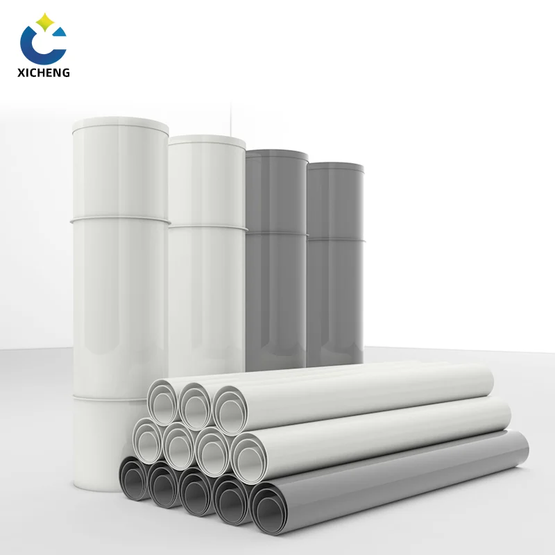
Isolation at analyzer gas lines
Industrial exhaust and fume systems carry more than air. Abatement trains — scrubbers, thermal oxidizers, VOC destruction units — routinely feed a continuous gas analyzer on a small sample line, and that line is inerted and supplied with calibration and fuel gas. The manual gas valve is the isolation that lets a technician change that analyzer, open its housing, or prove it dead without shutting down the whole abatement unit. It sits upstream of the sample take-off where the gas enters the instrument cabinet, in the same relationship the code gives an appliance shutoff: within reach of the instrument, upstream of the flexible supply line, and shut off on its own connection rather than on the branch feeding other instruments. In this role the manual valve is the plant-floor counterpart of the gas valve families described above — the same quarter-turn lever, the same positive proof of isolation, doing the same job a furnace shutoff does, but on a line that serves process instrumentation instead of a burner.
Corrosive vent and sampling lines
Where the duct or fume line carries acid vapour — from pickling baths, plating, or lab exhaust — the whole point of a control point is to keep the corrosion resistance intact through the valve. A brass or steel valve body at the take-off becomes the galvanic weak link: the fume that does not attack the PP duct will attack the metal valve body over a season, pit a seat, and present a leak where the run was otherwise sound. The sampling rules follow the duct rules, and the valve that matches the duct is the PP-bodied manual valve. On these lines the selection decision covered earlier — match the material to the media — is not an option but a requirement, and the valve body is chosen the way the plastic duct damper and PP duct damper are chosen for their runs: corrosion resistance has to hold from flange to flange.
The PP manual valve alternative
For fume and analytical gas duty where the media crosses both categories — a gas sample in a corrosive air stream, or a vent gas line that carries particulate and condensate — the practical answer is a manual valve in an engineering plastic. The manual air valve in the PP range gives hand operation and positive control with a body that matches the duct, which keeps a single material philosophy through the take-off instead of dropping a metal valve into a PP run. It is the same reasoning the manual air valve guide applies to compressed-air and ventilation service: choose the body for the media it must survive, and the manual mechanism for the control you need.
Where a sampling or vent line also needs a vent or drain point, combine the isolation valve with the bleed point — the manual bleed valve guide shows how the two work together at a low point or a tee. For a project that couples a gas control point into fume ductwork, the engineering team can size the take-off, the valve, and the drain together.
Manual Gas Valve FAQ
What is a manual gas valve?
A manual gas valve is a hand-operated valve that starts, stops, or throttles the flow of fuel gas in a piping system. It has no motor, solenoid, or thermostat — turning a lever, knob, or handwheel moves a ball, plug, or stem into or out of a seat, and the valve holds that position until someone changes it. It is the valve used to isolate a meter, a regulator, or an appliance so the line can be proven dead.
How does a manual gas valve work?
A quarter-turn type rotates a ball or tapered plug so its bore lines up with the pipe to open, or presents a solid face to the flow to close; the handle is parallel to the pipe when open and perpendicular when closed. A multi-turn type spins a threaded stem that lowers a disc, wedge, or needle into a seat. Lubricated plug valves keep their seal with a film of sealant injected through a lube port, which lets them be relubricated in place.
What is the difference between a manual and an automatic gas valve?
A manual gas valve is opened and closed by a person and holds its last position, which makes it a positive, physical proof that a line is off. An automatic gas valve is opened and closed by a thermostat, timer, or sensor to control temperature and demand. Combination gas valves add pressure regulation and pilot ignition in one body. Automatic and combination valves manage the appliance day to day, but a manual shutoff valve is still installed upstream of them so an operator can prove the line dead.
How do you tell if a manual gas valve is open or closed?
On a quarter-turn valve, read the lever: parallel to the pipe means the valve is open, perpendicular means it is closed. On multi-turn valves there is no visible position indicator, so the procedure is to close the valve fully, tag it, and prove the line dead with a downstream test rather than trusting the handwheel position. Lockable handles can be pinned shut to prevent accidental opening.
Can a manual gas valve be used on duct and fume lines?
Yes, beyond burner trains a manual gas valve isolates analyzer supply at abatement trains and gas sample take-offs on industrial ductwork. Where the fume is corrosive, the valve body should match the duct material — a PP-bodied manual valve keeps corrosion resistance through the take-off the same way the duct run does. A manual shutoff can be paired with a bleed point to drain or vent a low section safely.
Key Takeaways
A manual gas valve is the hand-operated positive shutoff behind every automatic and combination gas valve — it proves a line is dead where an automatic valve only manages the flow.
Quarter-turn ball and plug valves are shutoff valves; multi-turn globe, needle, and butterfly valves are throttling valves. Fit the listed shutoff upstream of any throttling valve, always. An electric butterfly valve automates that throttling butterfly where a gas or process line must control flow under power.
Read the body markings, not the catalogue: WOG does not cover combustible gas — ½ PSIG, 5G, and 125G do — and UL, CSA, FM, and CGA marks are the record an inspector verifies.
Code locations matter: an appliance shutoff valve sits in the same room as its appliance, within 6 feet of it, upstream of the union or connector, and never in a concealed location or furnace plenum.
On corrosive fume and analytical gas lines, choose the valve body to match the duct — a PP-bodied manual valve keeps corrosion resistance through the take-off where a metal body becomes the weak link.
