
Electric Exhaust Valve: One Name, Two Products
Search for an “electric exhaust valve” and you will find two completely different machines under the same name. On one side is the automotive exhaust cutout, a 12-volt butterfly valve welded into a car’s exhaust pipe that opens a bypass around the muffler to make the engine louder. On the other side is the industrial electric exhaust valve, a motorized damper in an exhaust duct that opens, closes, and holds intermediate positions to control how much fume an exhaust system moves through a building, scrubber, or lab hood. The name is shared; the duty, the voltage, and the customer are not.
This guide separates the two machines and then focuses on the industrial motorized electric exhaust valve that regulates airflow on exhaust ductwork. It covers the code that requires motorized shutoff on exhaust ducts, the corrosive streams the valve must survive, control signals, fail positions, sizing, and the one-piece engineering-plastic bodies that keep the damper leaktight on acid and solvent fume lines. The wider electric valve family is covered in the pillar guide, and the general disambiguation of powered duct dampers against solenoid air valves is handled in the electric air valve guide; here the medium is exhaust air, and every trade-off follows from the fact that the valve lives inside the corrosive stream it is moving out of a facility.
The Industrial Electric Exhaust Valve
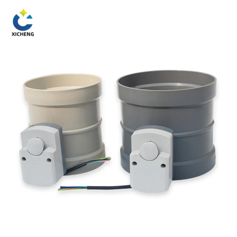
The industrial electric exhaust valve is a motorized damper installed in a section of exhaust ductwork. Its body is a short length of round or rectangular duct, usually from about DN50 up through DN315 and beyond, with a blade that pivots across the bore on a central shaft. An electric actuator on the side of the body drives the shaft through a reduction gear train, so the blade rotates from parallel with the flow, fully open, to across the flow, closed, and stops at any commanded angle in between.
The job is flow control, not sound. In a fume or ventilation exhaust system the valve shuts a line off when the process behind it is idle, trims airflow to hold a face velocity or static pressure while it runs, isolates a section for maintenance or fire containment, and prevents backdraft when a fan stops. It answers a building controller with 0-10 V or 4-20 mA signals, holds its position mechanically with zero power draw, and is specified in corrosion-resistant plastics because the stream it controls is by definition the hazard being removed from the building. The drive train and actuator-sizing detail behind this duty are covered in the electric valve actuator guide.
The Automotive Exhaust Cutout
The automotive electric exhaust cutout is a compact 12-volt butterfly valve that bolts or welds into a car’s exhaust pipe just ahead of the muffler. When the blade is closed, exhaust flows through the normal muffler path and the car stays quiet. When the blade opens, exhaust takes a shorter, unrestricted bypass and exits the system early, which cuts backpressure, adds power at the track, and produces the loud sound the driver is asking for. It is controlled from a rocker switch or remote in the cabin, and OEM systems on some production cars use an exhaust valve in the same position to switch between efficient and sport exhaust modes.
Everything about the two machines is different: the automotive cutout is wired to a car battery through a relay and fuse, opens in about a second, and exists to make noise or unlock a few horsepower; the industrial electric exhaust valve sits in a duct run at building scale, strokes in tens of seconds, and exists to move toxic or process air safely. The car part is typically illegal to use open on public roads in most states, while the industrial damper is frequently required by building and mechanical code. A shopper who types “electric exhaust valve” is generally looking for the motorized duct damper this manufacturer builds, not a muffler bypass, and the rest of this guide covers that product.
| Factor | Industrial electric exhaust valve | Automotive exhaust cutout |
|---|---|---|
| Location | Exhaust duct in a building, scrubber, or lab system | Exhaust pipe on a car, ahead of the muffler |
| Element | Motorized damper blade across a duct bore | 12-V butterfly valve in a round exhaust tube |
| Supply | 24 V DC or mains AC through a controller | 12 V DC from the vehicle battery, relay and fuse |
| Command | 0-10 V, 4-20 mA, or fieldbus for modulation | Rocker switch or remote, open or closed |
| Purpose | Shutoff, modulation, isolation, backdraft prevention | Sound and reduced backpressure |
| Stroke | Tens of seconds, smooth, adjustable | About a second, no intermediate hold |
| Materials | PP, PVC, or PPS for corrosive fume service | Mild or stainless steel exhaust tube |
| Regulatory | Required on many exhaust ducts by code | Street-illegal open in most states |
What an Electric Exhaust Valve Does in an Exhaust Duct
An exhaust system exists to capture contamination at its source and carry it out of the building, and the electric exhaust valve is the control point inside that network. It does not create the airflow; a fan does that. What the motorized damper delivers is the ability to open, close, and throttle each branch of the network on command, so that air is moved exactly where and when it is needed and kept out of occupied spaces the rest of the time.
Open, Close, and Everything Between
A basic electric exhaust valve operates in two positions: fully open to pass the required air and fully closed to stop it. On most exhaust duty the closed position is the important one, because an exhaust line left open lets conditioned air, heat, and in some cases fugitive fume leak where they are not wanted whenever the process behind the branch is idle. A closing-only motorized damper commonly pairs with a two-position actuator and just two end switches.
The more common industrial form adds modulation. A modulating electric exhaust valve responds to an analog signal and parks its blade at any intermediate angle, so the system can hold a constant face velocity at a capture hood as an operator moves, share airflow between scrubber beds, or trim static pressure as fan speed changes. The blade of a modulating damper is the throttling element, and its response is deliberately slow, moving over tens of seconds, so that slamming a large duct open or shut does not spike pressure and upset the fan or the process it serves.
Where It Sits in the Exhaust Train
In the standard exhaust train, source hoods and process vents feed branch ducts that merge toward a main duct, an exhaust fan moves the air, and a stack discharges it outside. The electric exhaust valve is mounted at the control points along that path: at each hood where it holds capture over a worker or a tank, at the inlet of a wet scrubber where it balances airflow against liquid chemistry, at zone take-offs where it shifts air between cleanrooms or process cells, and at the fan inlet or discharge where it trims the whole network. A relief or bypass damper on the stack performs the mirror-image duty, opening to protect the system from fan overpressure rather than closing to protect the building. Where the same damper carries make-up or outdoor air instead of fume, the shutoff and modulation rules are the same; the general powered-air control story is developed in the electric air valve guide.
The Code Behind Motorized Exhaust Dampers
Many exhaust ducts now carry an electric exhaust valve not because a process engineer chose one, but because energy codes and standards make the motorized damper a mandatory item. The requirement has been on the books for years and has only tightened as buildings have become better sealed and more energy-managed.
What the Code Text Requires
The relevant clause is IECC Section C403.2.4.4, Shutoff Damper Controls, mirrored by ASHRAE Standard 90.1 Section 6.4.3.4.2. Both read in substance: both outdoor air supply and exhaust ducts shall be equipped with motorized dampers that automatically shut when the systems or spaces served are not in use. Note the word and: the obligation covers the exhaust side every bit as much as the supply side. The exhaust opening is where conditioned air and thermal energy leave a building, so the code treats an un-dampered exhaust opening as the leak it is.
In practice the clause sends a motorized exhaust damper to several places: the exhaust duct that serves a space when the space is vacant or the system is off, the fan inlet so the fan does not recirculate through a dead duct, and the outdoor-air intake and exhaust penetrations that otherwise make a building breathe continuously. The damper can act on a schedule, on an occupancy signal, or on the run status of the fan itself. The shading message matters on fume work as well as energy: an unlocked exhaust duct is also a path for smoke, odors, and fugitive contamination when the system is idle. The full text with the exceptions is published in the model code, and the C403.2.4.4 code section is the place to cite it on a submittal.
The Three Exceptions
The code grants three carve-outs, and knowing them shows when a simple gravity damper can stand in for a motorized shutoff. Gravity dampers are permitted in buildings less than three stories in height; they are permitted in buildings of any height located in Climate Zones 1, 2, and 3, where energy leakage matters least; and they are permitted for outside-air-intake or exhaust airflows of 300 cfm (0.14 m3/s) or less. Outside those bounds the motorized damper is the mandatory form, and the electric exhaust valve described in this guide is the powered device that satisfies it.
There is a second, safety-side set of dampers that exhaust ducts also carry: fire and smoke dampers that are triggered by heat or smoke detection and close a duct penetration through a rated partition. A fire damper is a passive safety device that snaps shut on fusible-link or detector signal and is separate from the motorized control damper. Where the two overlap on one penetration, the project commonly specifies a combination fire-and-shutoff damper or coordinates the control damper’s closure schedule with the fire system’s, and the classification and testing details are treated in the plastic duct damper guide, which covers the full damper family for duct systems.
Four Jobs an Electric Exhaust Valve Performs
Underneath all the label differences, any electric exhaust valve on an exhaust network is doing one of four jobs: shutting a line off, trimming a flow, isolating a section, or blocking a reversal. Recognizing which job a particular damper is assigned keeps the specification honest, because a valve picked for the wrong job is either spending money on modulation it never uses or failing to close tightly enough to protect a space.
Shutoff and Fan Interlocks
Shutoff is the code-driven role from the previous section: the damper closes the exhaust duct when the served space or process is not running, so the building stops losing conditioned air and potential fume paths close automatically. On fan systems the shutoff damper normally travels together with the fan, opening when the fan starts and closing when it stops, so that a parked fan never becomes a free path for backflow or smoke.
Sequencing with the fan starter
Reliable sequencing is the detail that makes shutoff work. The damper should be wired so that its control interlock with the fan starter holds the blade closed while the fan is off, opens it as the fan comes up to speed, and closes it again before the fan is stopped, in the order that prevents pressure transients and fugitive release. On a building automation network the schedule lives in the controller, and the actuator reports its position and alarm state back so an interlock failure is visible from the control room rather than discovered by smell.
Modulation for Constant Flow
Modulation is the continuous-balancing job. A fume hood must hold a constant face velocity as an operator walks past it, a multi-bed scrubber must share airflow as beds load and unload, and a manifold must trim static pressure as individual branches start and stop. A modulating electric exhaust valve answers the controller’s 0-10 V or 4-20 mA demand and parks its blade at the needed angle, moving in small, slow steps rather than slamming between limits, and the control loop around it handles the correction. Manufacturers report sub-degree position repeatability on good actuators, which is the granularity a tight pressure loop needs.
Isolation with a Full-Perimeter Seal
Isolation is the maintenance and containment job: the damper seals a section of duct completely so people can work on a fan, a scrubber bed, or a downstream stack without the rest of the network breathing into the job. Isolation dampers trade cost and clearance for a tight boundary, using a full-perimeter seal around the blade so leakage stays low when the damper is closed. The same low-leakage design shows up on laboratory exhaust isolation duty, where a laboratory must hold contamination out of a shutdown line, and industrial-lab exhaust damper lines are built around exactly that seal detail. On duct breeding fume, a small leakage rate adds up over a shift, so the isolation spec is where the leakage class of the next section really matters.
Backdraft Prevention
Backdraft prevention is the one-way job. An exhaust fan moving air in one direction, and a wind shift, a stack effect, or the failure of one fan in a parallel bank can push air backward through a parked duct. A backdraft damper lets air travel in the designed direction and closes against reverse flow, either as a counterbalanced blade that opens on forward velocity or as a dedicated one-way element. The electric exhaust valve performs the same protective role when it closes automatically on fan-stop, and on the manual unpowered side the family of one-way and blast-gate dampers is surveyed in the manual air valve guide. A louver or multiplicity of small blades open and close as a bank; the mechanisms across damper and louver types are catalogued in the damper reference.
Matching the Electric Exhaust Valve to the Exhaust Stream
An exhaust system exists to move something unpleasant, and the electric exhaust valve sits directly inside that stream, so its body material is a selection decision and not an afterthought. A damper that controls clean ventilation air can be painted steel; a damper that controls the fume a factory is paying to remove must survive the chemistry it is carrying, and that changes the whole construction.
Why Metal Dampers Fail on Fume Exhaust
Wet scrubber, plating, pickling, and solvent exhaust streams are damp mixtures of acid or alkaline vapour, and they corrode a metal blade and casing steadily. Galvanized and painted steel lose their coating at cut edges and shaft seals, and the corrosion products are carried up the duct and along the blade, where they also attack the shaft bearings and the blade seal that the damper needs to close tightly. The failure is gradual rather than an instant break: increasing torque, a blade that no longer seats, corrosion that eventually jams the shaft. On the streams this manufacturer’s valves are specified for, the answer is not a stronger metal but to remove metal from the wetted envelope entirely.
PP, PVC, or PPS: One Body, Three Chemistries
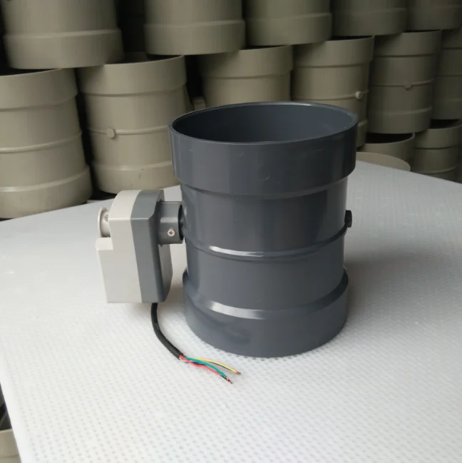
The industrial electric exhaust valve used on corrosive fume is moulded as a one-piece body in an engineering plastic matched to the stream. One-piece injection moulding is the construction point that deserves emphasis: it removes the welded seams and micro-pores of a fabricated plastic damper, the exact features through which thin fume escapes and at which corrosion starts, and gives the valve a genuinely tight envelope against leakage.
| Body material | Best exhaust duty | Strength |
|---|---|---|
| PP (polypropylene) | Wet scrubber and plating-fume networks | Wide acid and alkali resistance, lowest cost per diameter |
| PVC (rigid) | Plating and aggressive solvent fume where the duct is itself PVC | Mechanical rigidity, structural strength, chemical inertness |
| PPS (polyphenylene sulfide) | Hot-gas and combustion-adjacent exhaust | Dimensional stability and flame retardance under thermal load |
Polypropylene is the everyday workhorse: it resists the broad acid and alkali range that covers most scrubber and plating exhaust, welds and forms readily, and carries the lowest installed cost, which makes the PP electric exhaust valve the default on acid ventilation networks where cost per diameter governs. PVC takes over where rigidity matters as much as chemistry, particularly where the surrounding duct is PVC and the damper must match it. PPS is the high-temperature member, keeping its shape and its flame-retardant character on process lines whose thermal load is beyond PP and PVC. The base material behaviour, from density and temperature rating to chemical resistance and welding, is developed at length in the polypropylene sheet properties guide, which covers the same family of sheet used to build the duct around these dampers.
Control Signals, Fail Positions, and Wiring
The electric exhaust valve earns its place when it can answer the building or process controller, so the electrical interface deserves as much attention as the drive. Three decisions settle the wiring and control of any exhaust damper: whether it switches or modulates, what it does on loss of power, and how it talks to the control system around it.
On/Off or Modulating
An on/off electric exhaust valve carries a two-position actuator with end switches, sees a digital command to open or close, and is the right form for pure shutoff and isolation duty. A modulating valve carries an actuator with a position feedback element and accepts an analog or fieldbus command to hold a specific angle. On duct networks the two are ordered differently and priced differently: shutoff logic on a code-required exhaust damper wants on/off, while a balancing or hood-tracking damper wants modulation. On the supply and fresh-air side, the same on/off-versus-modulating decision is drawn in the electric motorized damper guide, which treats outdoor-air intakes, zone branches, and economizer air-fraction control. Matching the actuator to the job avoids paying for a modulating head that only ever opens and closes, or fitting a bang-bang switch where a loop demands fine control.
Fail-Safe Positions
What the blade does when power disappears is a safety question on an exhaust system, because the exhaust damper’s closed position may be the protection keeping fume or smoke out of a space. The two standard answers are a defined fail position and a hold-in-place position.
Spring-return fails to a defined position
A spring-return actuator stores enough energy in a spring or stored-energy device to drive the blade to a preset fail position when power is lost. On fume duty the common setting is fail closed, so a de-energized exhaust line seals shut against fugitive release; in cases where the equipment must keep breathing on power loss, the spec is fail open. The spring return travels the blade over a short time, generally seconds, and the actuator is the option to choose when the process or fire-safety logic demands a repeatable position on loss.
Self-lock holds the last position on zero power
A standard motorized electric exhaust valve holds its last position because the reduction gear train self-locks: reach the commanded angle, stop the motor, and the blade stays exactly there with no current drawn. This is the zero-power-hold behaviour that makes the motorized damper energy-efficient, drawing power only during its 30-to-90-second stroke and nothing while parked. The trade-off is that the last position is what you get on a blackout, so the hold-in-place form suits processes that can accept a frozen angle, while a code-required or contamination-critical shutoff pairs the self-locking drive with a spring return or with control logic that closes the damper before power is lost.
Speaking to the Building System
On a modern plant the exhaust damper is one node on a network. A building automation or PLC system issues the position demand, and a 4-20 mA loop is the industrial workhorse because current is immune to voltage drop over long cable runs and a broken wire reads as 0 mA, a recognizable fault. A 0-10 V signal is common on building automation, and intelligent actuators add digital fieldbus such as BACnet, Modbus, or Profibus, which carries position, torque, alarm, and cycle data back to the control room instead of a single position value. Whatever the protocol, the exhaust valve closes itself to a demand signal, to an occupancy or schedule input, and to the interlock with the fan from the earlier section, and reports back so the closed state is provable for both energy compliance and EHS audit. The control-valve loop that positions this family is explained further in the control valve reference.
Sizing, Leakage, and Performance
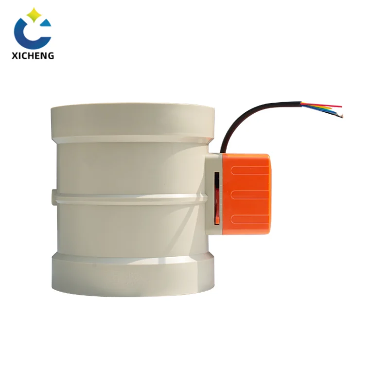
Sizing an electric exhaust valve is set by the duct, the fan, and the duty the damper has to perform. Four quantities decide the specification: duct diameter, duct velocity and static pressure, the required leakage class, and the stroke time the process can tolerate.
Diameter and Duct Velocity
Diameter follows the duct the valve is installed in, and the round electric exhaust valve spans roughly DN50 up through DN315 and beyond, with rectangular forms for rectangular duct runs. Velocity and static pressure come from the exhaust fan’s operating point, and the blade and shaft must carry the fluid force at that pressure; on low-pressure duct duty the differential across a throttled blade is modest, commonly a few hundred pascals, so the actuator torque demand stays small. The quarter-turn blade behaves like its pipe-side cousin the wafer butterfly, and the sizing and control-character treatment of that body is developed in the electric butterfly valve guide; on a duct the same blade simply runs at duct scale and duct pressure.
Stroke time is the performance figure the process cares about. A motorized damper traverses its quarter turn over tens of seconds, the valve described here working over a deliberate 30-to-90-second span, which prevents the pressure transient a fast slam would send down the duct. For shutoff and interlock duty a faster two-position head is available, and the designer trades stroke speed against the risk of pressure spikes on the specific network.
Leakage Class and Why Exhaust Cares
Containment and energy both hang on the damper’s closed-leakage figure, which is why an exhaust damper carries a leakage class rather than just a capacity. The AMCA 500-D standard classifies damper leakage; a low-leakage class, with the testing conducted at a specified static pressure such as 1 inch water gauge, certifies how much air bleeds past the closed blade, and the classes exist from very-low-leakage service up to less-controlled commercial forms. On exhaust duty the closed damper is often the barrier between an occupied space and a contaminated system, so the buyer should ask for the lowest-leakage class the application can justify and a leakage test witnessed at the pressure the duct actually sees.
Manufacturers that serve laboratory and industrial exhaust publish turns through low-leakage shutoff and isolation ranges built specifically for this service, because a laboratory exhaust riser that must hold contamination out of a shutdown line cannot accept the bleed of a cheap commercial damper. The plate on the spec sheet should name the class, the test pressure, and the seal construction, a full-perimeter blade seal being the detail that makes a stated low class believable on a fume duct.
Electric vs Pneumatic vs Solenoid vs Manual on Exhaust Duty
The motorized damper is not the only way to move an exhaust blade, and each driving method wins its own niches. The electric exhaust valve is usually the right default on a fume or ventilation duct, but the comparison explains why, and it is worth stating in one place.
A manual damper costs the least and needs nothing but a person to turn a handle, but it cannot respond to a controller, satisfy a code that demands automatic shutoff, or interlock with a fan, and it is useless on an inaccessible duct run; the unpowered drive head that does this job alone is covered in the manual valve actuator guide. A pneumatic actuator is fast and its spring return gives a defined fail position, but it needs a compressor, air tubing, filter regulators, and a positioner to translate an electrical command, infrastructure that is itself exposed to the same corrosive plant air the exhaust system handles. A solenoid is the fastest switcher of all, snapping a line open or closed in milliseconds, but it is strictly two-position and lives in the small-tube world rather than at duct scale, so on a DN200 fume duct it is not a horsepower contender; the full motorized-versus-solenoid comparison for air service is in the electric air valve guide.
| Driver | Supply | Modulates | Stroke | Fail on loss | Best exhaust duty |
|---|---|---|---|---|---|
| Electric (motorized) | Power cable, 0-10 V / 4-20 mA / fieldbus | Yes, any blade angle | 30-90 s, smooth | Self-lock holds; spring-return option | Duct shutoff, modulation, isolation, fan interlock |
| Pneumatic | Compressor, tubing, positioner | Yes | About 1 s | Spring return to defined position | Fast fail-safe where an air supply already exists |
| Solenoid | Coil, two-position only | No | Milliseconds | Spring returns or stays by type | Small pilot and safety lines, not duct scale |
| Manual | Handwheel or lever | By hand, not remotely | Human | Blade stays wherever left | Fixed balancing and rarely-touched straight runs |
On a corrosive fume duct the electric drive wins twice: it adds no air network for the corrosive plant air to damage, and at duct scale and duct pressure the modest fluid force means a small motor and gearbox hold the blade easily, with zero power consumed while parked. Where a line must be rebalanced occasionally but needs no automation, the manual counterpart is the low-cost choice, and the family of unpowered blade valves is catalogued through the manual bleed valve guide.
Installation, Commissioning, and Maintenance
An electric exhaust valve performs only as well as its installation and care routine, and on fume work the stakes are higher than comfort because the failing damper is the one holding contamination out of a space. Three practices keep it accurate and safe for years.
Installation starts with the mating surfaces. The duct flanges must line up freely, because flanges pulled into alignment with the bolts transfer distortion to the body and can bind the blade against its seal. The duct should be clean of welding debris and dust before the damper goes in, the blade is best left slightly open during welding on adjacent ductwork so heat does not warp a closed blade edge, and on plastic duct the joints around the damper follow the same welding rules as the rest of the fume line. The actuator needs clear space for its handwheel and local controls, and the cable glands must be made off properly to keep the enclosure rating: a loose gland quietly undoes an IP65 panel. Before energizing, confirm the supply voltage against the nameplate, because feeding 220 V to a 24 V drive destroys the electronics in seconds, then confirm the command direction so an increasing signal moves the blade the way the control strategy expects.
Commissioning verifies more than open and closed. Apply representative commands at 25, 50, and 75 percent and check that the blade settles at each value with the position feedback agreeing on the display, then confirm the open and closed travel limits and the fail action. Test the interlock with the fan from the earlier section by stopping the fan and watching the damper close on schedule. Then watch the installed damper during live operation: if the normal airflow holds the blade almost closed, the damper is oversized, and if the loop hunts around the setpoint, the controller is too aggressive for the installed response. On fuel-gas exhaust it repeats the pipe-side rule that a positive shutoff must sit upstream of any modulating element, a point developed in the manual gas valve guide.
Routine care covers both halves. On the body, watch for blade and flange leaks and for a changing operating torque, which can signal seal wear, deposits, or corrosion damage; fume deposits on a plastic blade are the real-world cause of a damper that stops seating. On the actuator, inspect the enclosure for moisture, test the manual override and local controls periodically, and compare the position feedback with the actual blade angle, because calibration drift makes the controller believe the damper is at an angle different from its true position. Dampers that modulate frequently benefit from cycle counts and torque trends, turning maintenance from a calendar task into a condition-based one. The product range for this duty, with sizes, actuator options, and the CE-marked motorized versions for mounting on fume networks, is the electric air valve line.
Buyers’ Checklist for an Electric Exhaust Valve
When procurement reaches the spec sheet, a short checklist separates a damper that will control an exhaust system for years from one that will be replaced mid-project. Work through the decision in the same order an application engineer does.
Must-Have Features
The features that matter split into the physical valve and the control head, and both must be matched to the duty before a model number is written down.
Materials and construction
Confirm the body, blade, shaft, and seals are compatible with the actual stream: PP, PVC, or PPS for acid, alkali, and solvent fume rather than painted steel, and a one-piece moulded body so there are no welded seams to leak or corrode. Note the stream temperature and confirm the chosen plastic’s rating for it. If the damper must isolate a space from a contaminated line, the seal construction and the leakage class must be specified and witnessed, not assumed.
Control and fail behaviour
State plainly whether the duty is shutoff or modulation. On/off duty wants a two-position actuator with end switches; regulating duty wants a modulating actuator, position feedback, and the duty rating to make many small movements a day. Specify the supply voltage, the command signal resolving 0-10 V against 2-10 V, and the fail position on loss of power: hold-in-place with the self-locking drive, or a spring-return to the defined position the safe-shutdown logic demands. Then confirm the interlock input for the exhaust fan so the damper is provably closed with the fan stopped.
Documents to Request
Close the loop with paperwork, because an exhaust damper is a compliance item as often as a commodity. Ask for the leakage class and the test method and pressure behind it, the actuator torque and stroke-time data, the wiring diagram with the fan-interlock terminal named, and the material certificates for stream compatibility. Verify the certifications the market will ask for, CE for the electrical product and the ISO and RoHS bases that the surrounding plant expects, and request the cycle or duty rating where the damper modulates frequently. Then ask the supplier for the exact installed-flow and actuator calculation rather than a diameter-based guess, which is where a modulating exhaust valve is most often oversized and its loop reduced to hunting.
Electric Exhaust Valve FAQ
Is an electric exhaust valve the same as an exhaust cutout?
No. The two share a name but little else. An automotive exhaust cutout is a 12-volt butterfly valve on a car’s exhaust pipe that bypasses the muffler to make the engine louder. An industrial electric exhaust valve is a motorized damper in a building’s exhaust duct that shuts off, modulates, or isolates fume airflow, answers a 0-10 V or 4-20 mA controller, and is often required by code.
Which exhaust ducts must have motorized shutoff dampers?
Under IECC C403.2.4.4 and ASHRAE 90.1 6.4.3.4.2, both outdoor air supply and exhaust ducts must have motorized dampers that automatically shut when the systems or spaces served are not in use. Gravity dampers are permitted only for buildings under three stories, buildings in Climate Zones 1, 2, or 3, or airflows of 300 cfm or less.
Can an electric exhaust valve modulate, or does it only switch?
Both forms exist. An on/off electric exhaust valve opens and closes on a digital command for shutoff and isolation duty. A modulating electric exhaust valve accepts an analog 0-10 V or 4-20 mA signal and parks its blade at any intermediate angle, which is what hood face-velocity control, scrubber balancing, and static-pressure trimming require.
What happens to the exhaust valve on a power failure?
A standard motorized electric exhaust valve holds its last position because its reduction gear train self-locks, drawing no power while parked. If the process demands a defined fail position, the actuator is specified with a spring return that drives the blade to a fail-open or fail-closed angle, with fail closed being the usual setting on fume duty.
What materials suit a corrosive fume exhaust valve?
For acid, alkali, and solvent streams the body is specified in PP, PVC, or PPS rather than painted steel, moulded in one piece to remove the welded seams that leak and corrode. PP covers most scrubber and plating exhaust, PVC adds rigidity for aggressive streams, and PPS covers hot-gas duty. One-piece construction keeps the closed damper genuinely leaktight on fume networks.
Why do the blades open and close so slowly?
A motorized electric exhaust valve strokes its full quarter turn over roughly 30 to 90 seconds deliberately. Moving a large duct blade in a fraction of a second would spike static pressure and disturb the fan and the process; the slow, smooth stroke keeps the flow transient invisible, and the self-locking drive then holds the blade in place with zero power.
Key Takeaways
“Electric exhaust valve” names two machines: the automotive exhaust cutout that bypasses a muffler for sound, and the industrial motorized exhaust damper that shuts off, modulates, and isolates fume airflow in a duct. Match the machine to the duty before reading a catalog.
IECC C403.2.4.4 and ASHRAE 90.1 6.4.3.4.2 require motorized shutoff dampers on exhaust ducts as well as supply ducts, closing automatically when the served space or system is idle, with gravity dampers permitted only under narrow exceptions.
An electric exhaust valve performs four jobs: shutoff with the fan interlock, modulation for constant flow, isolation with a full-perimeter seal, and backdraft prevention, and each job dictates a different spec.
On corrosive fume the valve body is a one-piece PP, PVC, or PPS moulding, not painted steel, so there are no welded seams to leak or corrode inside the very stream the system exists to remove.
The motorized drive draws power only during its 30-to-90-second stroke and self-locks in place afterwards; a spring-return option supplies the defined fail position that fume-safe logic may demand.
An electric exhaust valve is the control point in a building’s exhaust network: a self-locking motorized damper that closes automatically when the system is idle, holds face velocity and static pressure while it runs, isolates a contaminated line on command, and survives the acid and solvent stream it is moving. Specify the job first, shutoff, modulation, isolation, or backdraft prevention, then match stream chemistry, voltage, control signal, and fail position, and the damper will earn its place for years. The full powered range of the family is the electric valves line, the motorized duct-damper product for this duty is the electric air valve page, and the engineering desk at contact us handles torque, leakage, and CAD layout for specific exhaust networks.
